
A high-response hydraulic servo tool holder system for boring and a machine tool with the system

A hydraulic servo and high-response technology, applied in the direction of boring head, manufacturing tools, boring/drilling, etc., can solve the problem of difficult to adapt to variable ellipse and irregular non-circular shape processing, wedge slider mechanism friction and structural rigidity , can not realize the radial feed movement and other problems, achieve high precision, realize precise control, and improve the effect of control accuracy

Inactive Publication Date: 2019-12-24
SHANDONG UNIV
View PDF6 Cites 0 Cited by
  • Summary
  • Abstract
  • Description
  • Claims
  • Application Information

AI Technical Summary

Problems solved by technology

[0006] (2) It is impossible to change the relative position of the tool relative to the axis of the tool holder (or the axis of the spindle), and the radial feed movement cannot be realized;
[0007] (3) Combining with other feeding methods described later, it can form the boring of "flare mouth + fixed ellipticity" special-shaped pin holes, but it is difficult to adapt to the machining of variable ellipse and irregular non-circular shapes.
However, the wedge-shaped slider mechanism has friction and structural rigidity problems, and is also not suitable for high-response applications.
[0013] Zhejiang University, Shanghai Jiaotong University, etc. have also conducted research on other types of elastic deformation methods, and conducted experiments, and achieved some results, but have not yet formed a mature mechanism that can be applied to production
Japan's Kanzaki and Longze companies used the elastic deformation body of NT company to realize the boring of the special-shaped pin hole of the bell mouth, but there is no report on the high-speed precision boring of the complex three-dimensional space surface

Method used

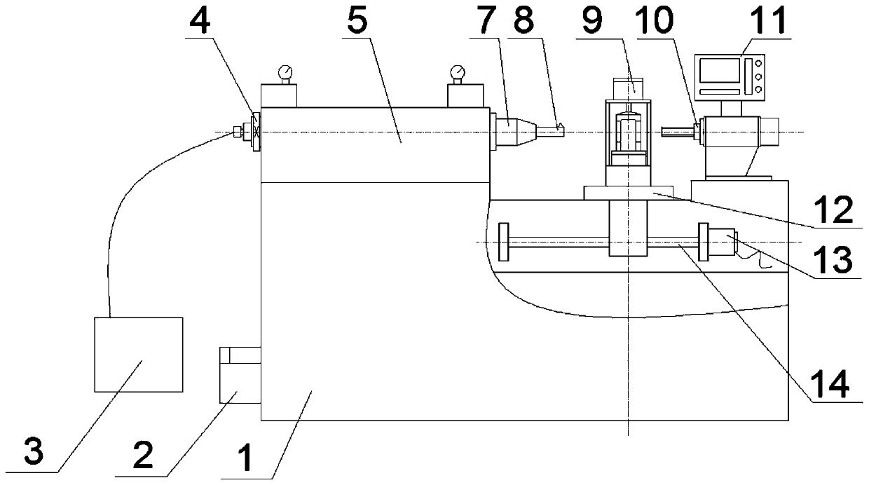
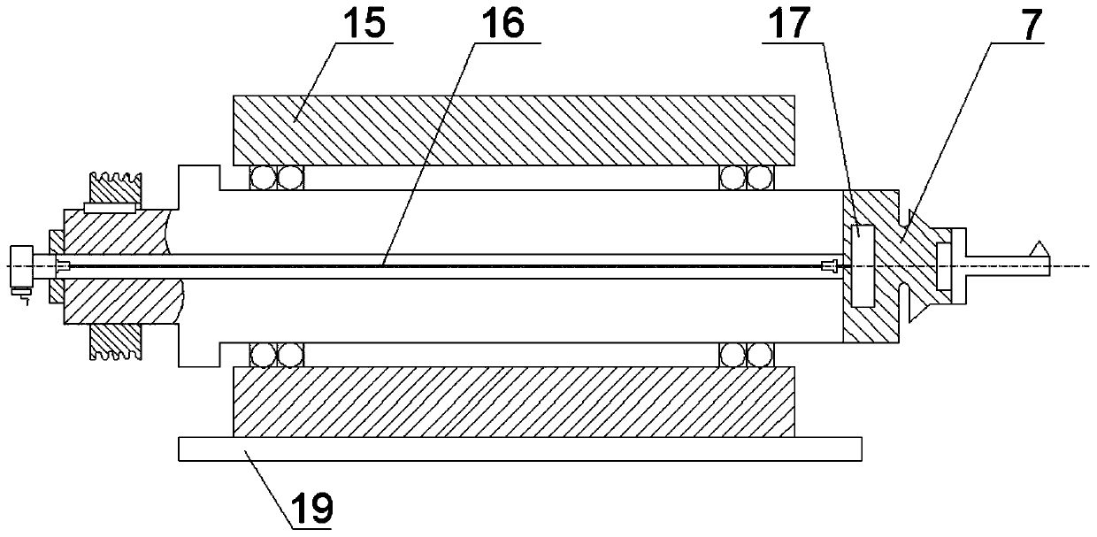
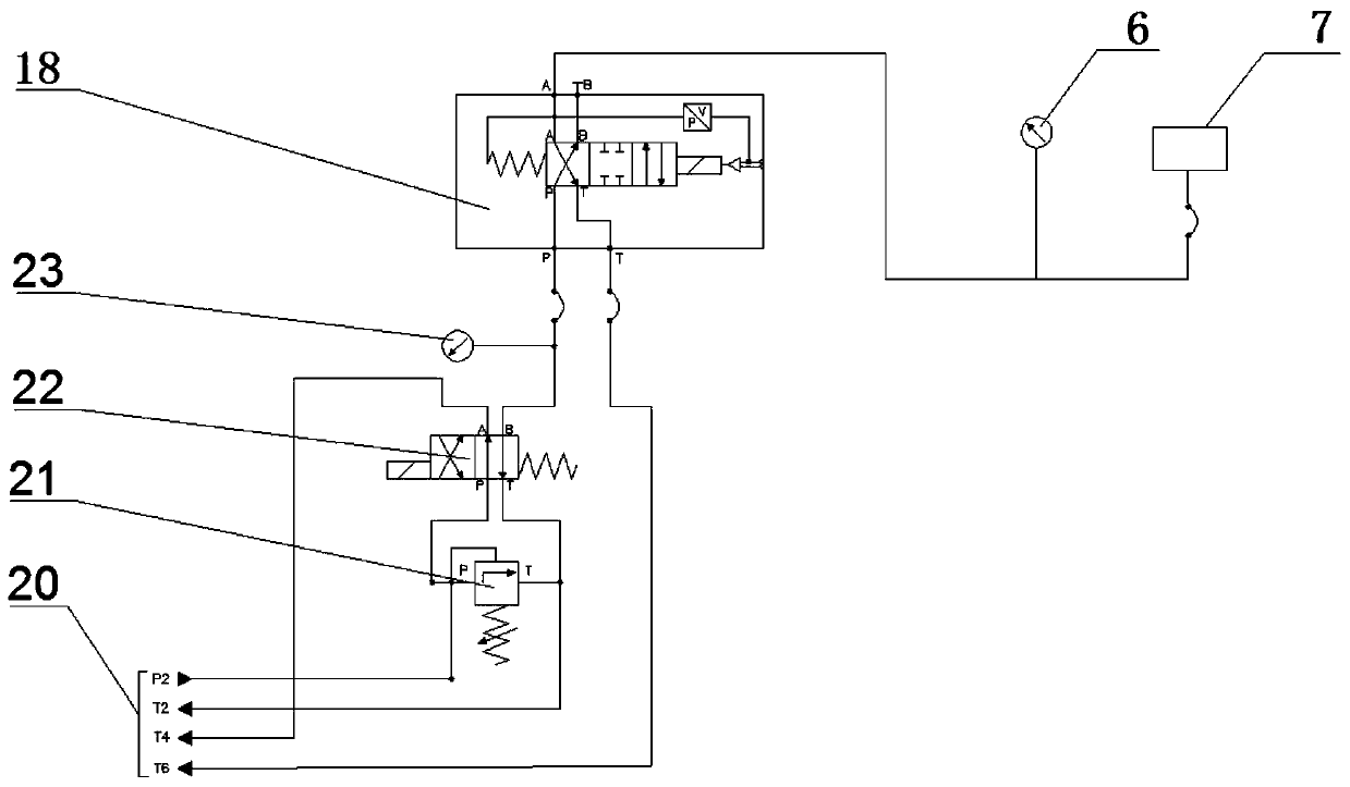

Image

  • A high-response hydraulic servo tool holder system for boring and a machine tool with the system
  • A high-response hydraulic servo tool holder system for boring and a machine tool with the system
  • A high-response hydraulic servo tool holder system for boring and a machine tool with the system

Examples


Embodiment Construction

[0047] It should be pointed out that the following detailed description is exemplary and intended to provide further explanation to the present application. Unless defined otherwise, all technical and scientific terms used herein have the same meaning as commonly understood by one of ordinary skill in the art to which this application belongs.

[0048] It should be noted that the terminology used here is only for describing specific implementations, and is not intended to limit the exemplary implementations according to the present application. As used herein, unless the context clearly dictates otherwise, the singular is intended to include the plural, and it should also be understood that when the terms "comprising" and / or "comprising" are used in this specification, they mean There are features, steps, operations, means, components and / or combinations thereof.

[0049] As introduced in the background technology, there is a deficiency in the prior art that the piston specia...


PUM


Abstract

The invention discloses a high-response hydraulic servo tool bar system for boring and a machine tool with the system, which solves the problem that the piston special-shaped hole processing equipment in the prior art is not suitable for high-response applications, and has the advantages of increasing the hydraulic servo The tool bar system is used as the third virtual axis to control the radial movement of the tool bar to achieve the effect of non-circular hole processing; its technical solution is to include an eccentric deformable body and a hydraulic station, and the hydraulic station includes a hydraulic station connected to the eccentric deformable body Servo valve: The servo valve controls the hydraulic oil according to the input voltage signal to obtain a pressure linearly related to the voltage signal. The hydraulic oil acts on the oil cavity inside the eccentric deformation body, and the eccentric deformation body realizes the radial direction of the boring tool under the action of the hydraulic oil. displacement compensation.

Description

technical field [0001] The invention relates to the field of boring equipment, in particular to a high-response hydraulic servo cutter bar system for boring and a machine tool with the system. Background technique [0002] The characteristics of the non-circular special-shaped hole surface are: the longitudinal section is a trumpet shape with both ends upturned; the cross section is non-circular, including ellipse and other asymmetrical curves. The servo control of the tool position during the boring process is the key to realize the machining of non-circular surface and special-shaped holes. [0003] According to the different radial feeding methods of the tool, the current domestic and foreign piston special-shaped hole processing equipment can be divided into: oblique cut type, mechanical imitation type and servo deformation tool rod type, etc. in, [0004] 1. The oblique cut type means that when the direction of the tool rotation axis is inclined to the axis direction ...

Claims


Application Information

Patent Timeline
Patent Type & Authority Patents(China)
IPC IPC(8): B23B41/04B23B29/034
CPCB23B29/03457B23B29/03478B23B29/03489B23B41/04
Inventor 翟鹏秦磊龙强王龙昌孙建浩韩宇珍杨润青陶祥力代勇魏一何磊刘维娟郭全喜
Owner SHANDONG UNIV
Learn More