Multi-angle machining roller manufacturing device

A manufacturing device, multi-angle technology, applied in the direction of injection device, manufacturing tool, grinding drive device, etc., can solve problems such as affecting production efficiency and reducing grinding efficiency of grinding wheels

Active Publication Date: 2019-07-19
TIANJIN SAIXIANG M&E ENG CO LTD
View PDF11 Cites 5 Cited by
  • Summary
  • Abstract
  • Description
  • Claims
  • Application Information

AI Technical Summary

Problems solved by technology

[0004] When the above-mentioned patent is grinding, because the contact surface between the grinding wheel and the

Method used


Image

  • Multi-angle machining roller manufacturing device
  • Multi-angle machining roller manufacturing device
  • Multi-angle machining roller manufacturing device

Examples


Embodiment Construction

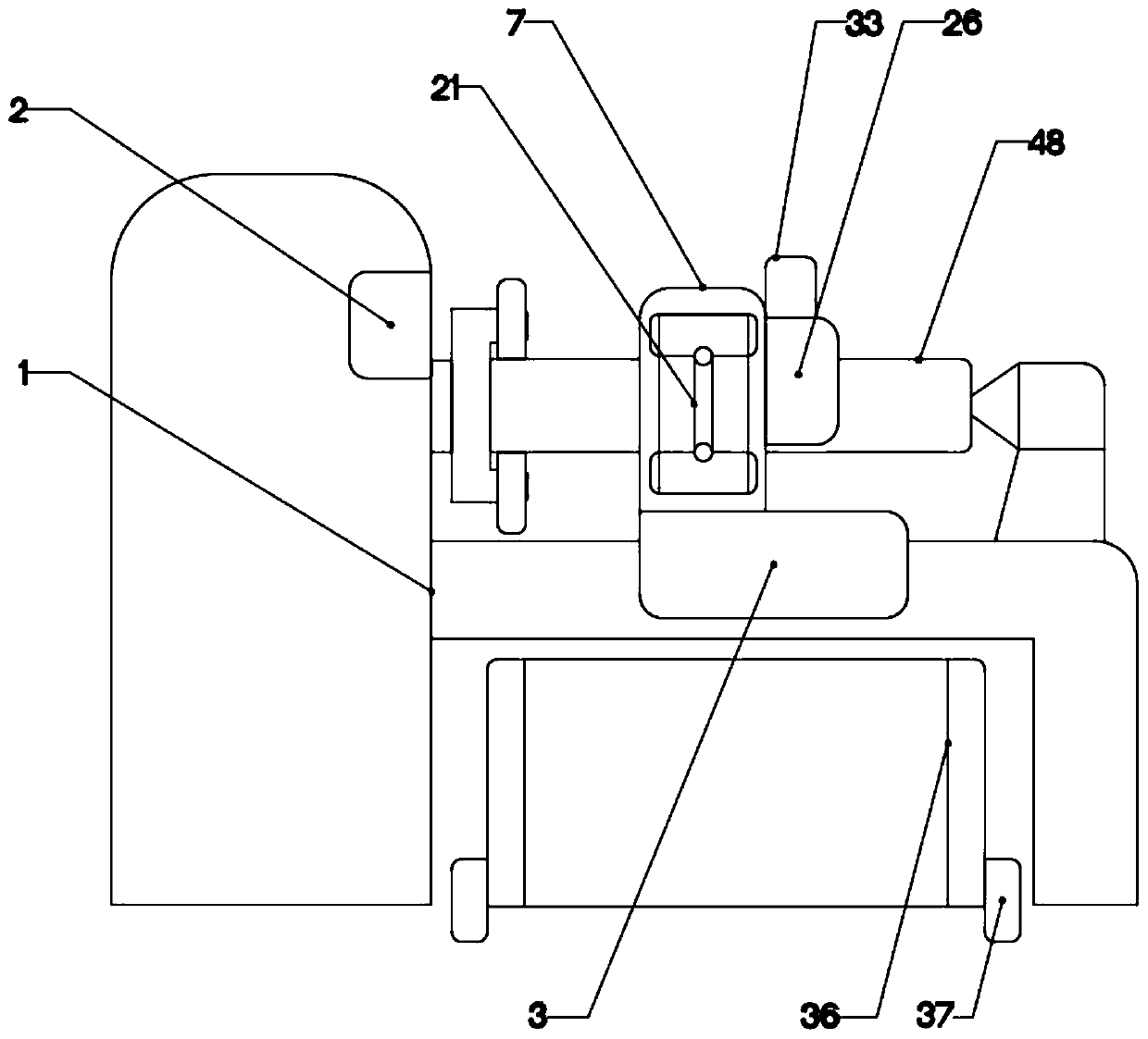
[0023] The present invention is specifically described below in conjunction with accompanying drawing, as Figure 1-5 shown.

[0024] In this embodiment, the model of the controller 2 is S7-200, and the signal output terminal of the controller 2 is connected with the pneumatic telescopic rod 1 6, the pneumatic telescopic rod 2 21, the air motor 1 15, the air motor 2 22, and the linear motor 1 30 , suction pump one 32, suction pump two 34, and the signal input terminals of the air pressure sensor 45 are electrically connected, and the power output terminal of the controller 2 is connected to the linear motor one 30, the suction pump one 32, the suction pump two 34, The power input end of the air pressure sensor 45 is electrically connected.

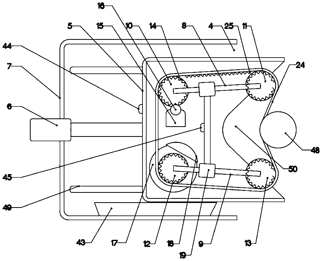
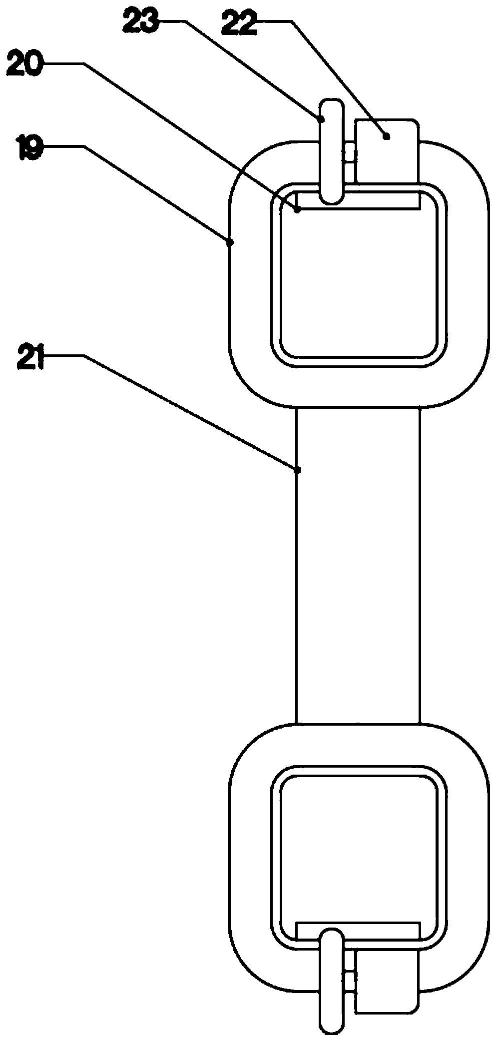
[0025] The invention point of the application lies in the structural design of the band grinding device, in this device in conjunction with the attached figure 2 and 3 , the belt-shaped grinding device can make the grinding belt 24 clo...


PUM


Abstract

The invention discloses a multi-angle machining roller manufacturing device. A lathe body is included. A roller buffering device is arranged on one side of the lathe body and is in sliding connectionwith the ground. A controller is arranged on the side surface of the lathe body. A strip-shaped grinding device is arranged above the lathe body. A circular oil applying device is arranged on one sideof the strip-shaped grinding device. The strip-shaped grinding device can make a strip-shaped grinding strip more attached to a roller through mutual cooperation of a fixed pulley and a movable pulley. The circular oil applying device can recycle surplus oil through the funnel collecting function. The multi-angle machining roller manufacturing device has the beneficial effects that operation is simple and convenient, and practicability is high.

Description

technical field [0001] The invention relates to the related field of roller processing, in particular to a multi-angle processing roller manufacturing device. Background technique [0002] The production of drum-shaped rollers requires very complicated processes, such as assembly, welding, axle, polishing, oiling and maintenance, etc. If the axle can be polished and oiled at the same time, the processing time will be greatly saved. [0003] In the patent No. 201520872886.9, a movable copper roller automatic grinding device, the mobile trolley is pushed to the frame of the copper roller, so that one end of the third pallet of the lateral movement device corresponds to the positioning block. Manually or mechanically control the hydraulic cylinder of the mobile trolley to descend, so that the third supporting plate is located on the bracket between the positioning block and the fixed plate. Jogging controls the lateral moving device to move until the grinding wheel is located ...

Claims


Application Information

Patent Timeline
IPC IPC(8): B24B21/02B24B21/20B24B41/00B24B47/12B24B47/22B24B49/16B24B55/08B05B13/04B05B14/00
CPCB05B13/0421B24B21/02B24B21/20B24B41/005B24B47/12B24B47/22B24B49/165B24B55/08B05B14/00Y02P70/10
Inventor 郑肖
Owner TIANJIN SAIXIANG M&E ENG CO LTD
Why Eureka
Try Eureka