DC heavy-current measuring device and measuring method

A measuring device and high-current technology, applied in the direction of measuring device, measuring electrical variables, measuring only current, etc., can solve the problems of affecting compensation current size, measurement error, measurement error amplification, etc., to achieve small measurement impact, high measurement accuracy, The effect of stable work

Active Publication Date: 2019-07-19
WUHAN UNIV
View PDF17 Cites 3 Cited by
  • Summary
  • Abstract
  • Description
  • Claims
  • Application Information

AI Technical Summary

Problems solved by technology

This method does not have the obvious disadvantages of the previous methods, but because the iron core is often in a saturated state, it cannot measure the harmonic components in the DC current, nor can it reflect the transient process of the current; at the same time, the harmonic components in the excitation current will also Affects the size of the compensation current and brings errors to the measurement
In order to measure the transient and harmonic components in DC current, Rogowski coils can be used together, but this will increase the complexity of the measurement, and numerous signal processing links will gradually increase the measurement error
[0010] It can be seen that in order to meet the accuracy of measuring DC large current, anti-electromagnetic interference, and anti-seismic performance, the above technologies still cannot meet the measurement requirements.

Method used


Image

  • DC heavy-current measuring device and measuring method
  • DC heavy-current measuring device and measuring method

Examples


Embodiment Construction

[0025] Embodiments of the present invention will be described in detail below in conjunction with the accompanying drawings.

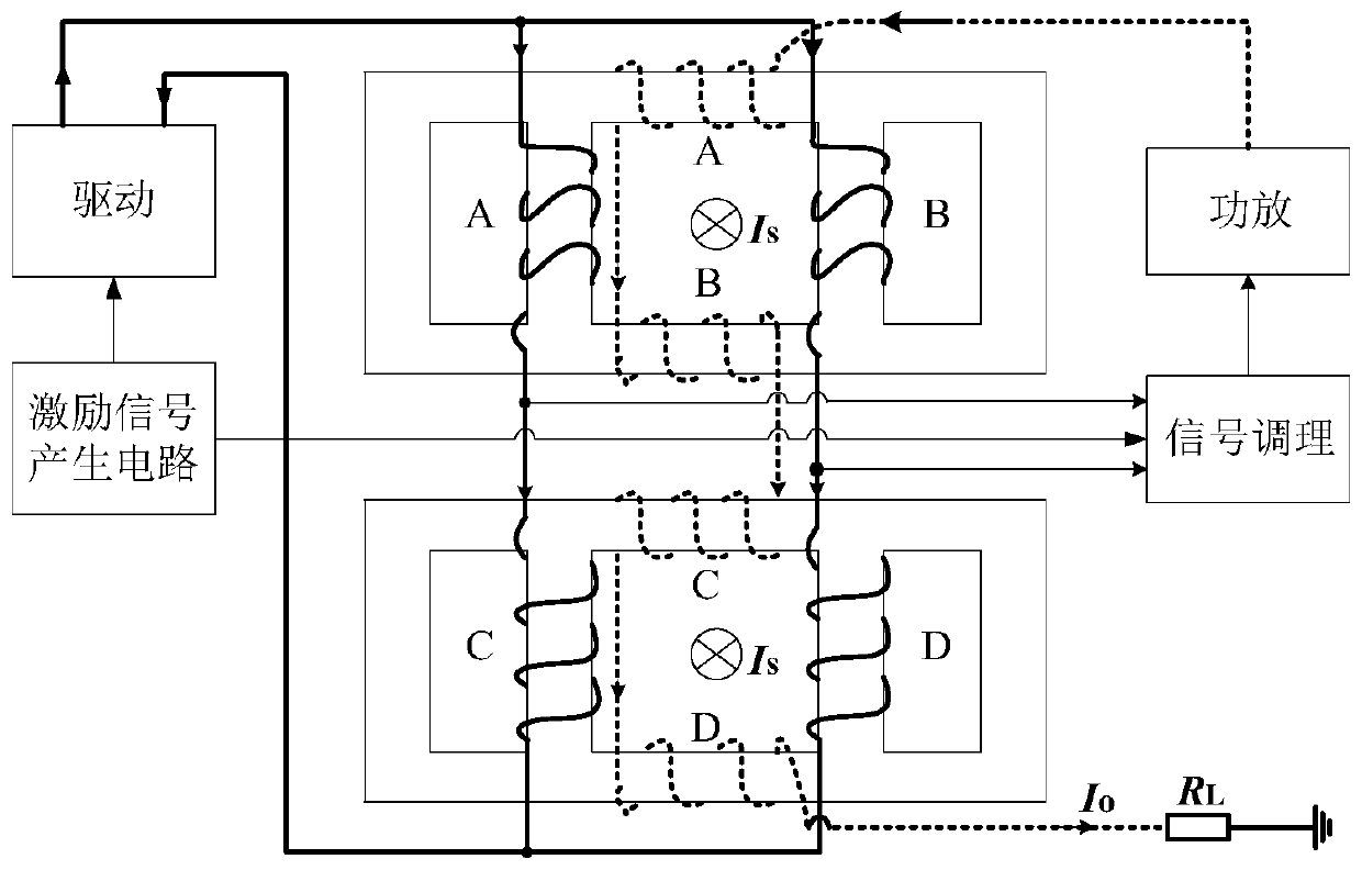
[0026] This embodiment provides a DC large current measuring device, including a four-column iron core, first, second, third, and fourth excitation windings, first, second, third, and fourth compensation windings, and an excitation signal generating circuit , drivers, signal conditioning circuits, power amplifiers and standard resistors.

[0027] There are two sets of four-column iron cores, stacked front and back, and the current to be measured passes through the holes in the middle of the two sets of iron cores. The first excitation winding A and the second excitation winding B with the same number of turns are wound on the middle two columns of the four-column iron core at the rear, and the first compensation winding A' with the same number of turns is wound on the middle two horizontal columns. And the second compensation winding B', corresponding...


PUM


Abstract

The invention relates to a current measurement technology of electrotechnics and specifically to a DC heavy-current measuring device and measuring method. The device comprises a four-column iron core,an excitation winding, a compensating winding, an excitation signal producing circuit, a driver, a signal conditioning circuit, a power amplifier and a standard resistor. The measuring method comprises the steps of converting electrical current flow to magnetic flux for detection; realizing magnetic circuit splitting through cooperation of a special iron core structure and the bridge-type connected excitation winding; and after performing signal processing on the middle-point voltage difference of the bridge-type connected excitation winding, controlling the current of the compensating winding to enable the magnetic flux to recover balance. Problems such that a zero-magnetic-flux current sensor feedback detection circuit is complex, the compensating current has excitation signal ripple waves, and the transient current and harmonic current are difficult to detect.

Description

technical field [0001] The invention belongs to the technical field of current measurement in electrotechnical technology, and in particular relates to a direct current large current measuring device and a measuring method. Background technique [0002] The application of DC high current in modern industry is quite extensive, among which metallurgy and electrolytic plating are the most common. The continuous development and application of DC transmission technology also put forward requirements for the measurement of DC large current. In addition, some scientific research requires the use of particle accelerators, high-power power electronic equipment, high-power batteries, etc., all of which involve the measurement of DC large currents, and its importance is self-evident. [0003] For energy storage devices such as high-power batteries, the timely and accurate detection of their output current is an indispensable part of testing the electrical performance of the battery. ...

Claims


Application Information

Patent Timeline
Patent Type & Authority Applications(China)
IPC IPC(8): G01R19/00
CPCG01R19/0092
Inventor 陈柏超陈耀军田翠华吴凡
Owner WUHAN UNIV
Why Eureka
Try Eureka