
Transverse flux permanent magnet motor of axial magnetic field flux switching type

A technology of magnetic flux switching and transverse magnetic flux, applied in the direction of magnetic circuit shape/style/structure, magnetic circuit, electric components, etc., can solve the problems of excessive axial length, difficult power, complex structure and process, etc. The effect of volume and complexity, reducing maintenance difficulty, and improving fault tolerance performance

Pending Publication Date: 2019-07-19
HEBEI UNIV OF TECH
View PDF0 Cites 9 Cited by
  • Summary
  • Abstract
  • Description
  • Claims
  • Application Information

AI Technical Summary

Problems solved by technology

However, the structure of the traditional transverse flux permanent magnet motor is not perfect. If the existing transverse flux motor needs to increase the torque density or increase the number of motor phases, it needs to connect multiple stators with the same structure coaxially. Complicated and only suitable for long shaft applications due to their long axial length
Moreover, when most transverse flux permanent magnet motors are used as multi-phase motors, the axial length will be too large, which will lead to a large iron loss.
In addition, the permanent magnets of the traditional transverse flux motor are installed on the rotor, resulting in poor heat dissipation of the motor, and it is not easy to provide higher power
[0003] Therefore, how to solve the problem of large volume and complex structure while optimizing the performance of transverse flux permanent magnet motor has become an important issue.

Method used


Image

  • Transverse flux permanent magnet motor of axial magnetic field flux switching type
  • Transverse flux permanent magnet motor of axial magnetic field flux switching type
  • Transverse flux permanent magnet motor of axial magnetic field flux switching type

Examples


Embodiment 1

[0058] In the transverse flux permanent magnet motor of the axial magnetic flux switching type in this embodiment, each single-phase motor module is a double-stator single-rotor structure (see Figure 7 and Figure 8 ), that is, a single-phase motor module includes a rotor and two stators,

[0059] The motor adopts a double-stator single-rotor structure, and the stator includes two parts: a special-shaped stator core and a special-shaped permanent magnet (in this embodiment, the stator core and the permanent magnet are U-shaped stator cores and U-shaped permanent magnets), and the special-shaped stator core and special-shaped permanent magnets Alternately arranged along the circumferential direction to form a flux-switching annular structure stator, there is a stator ring groove on the stator, the direction of the stator ring groove is parallel to the rotating shaft, and a ring winding is arranged in the groove. The number of stator cores is M, the number of special-shaped pe...

Embodiment 2

[0064] The axial magnetic flux switching type transverse flux motor in this embodiment has a high power density, high efficiency, thin structure and simple structure, including a rotor, a special-shaped stator core, a special-shaped permanent magnet, and an armature winding.

[0065] The motor adopts a double-rotor single-stator structure (see Figure 10 ), the stator consists of two inner and outer flux switching stator rings (see Figure 11 ) (the relative positions of the inner and outer circles are as shown in the figure), and each circle is composed of special-shaped permanent magnets and special-shaped stator cores arranged alternately along the circumference to form a ring shape (the stator core and permanent magnets in this embodiment are fan-shaped cylindrical stator cores and fan-shaped cylindrical permanent magnets. magnet (see Figure 19 and Figure 20 )). There is a one-to-one correspondence between the permanent magnets of the inner and outer rings and the pos...

Embodiment 3

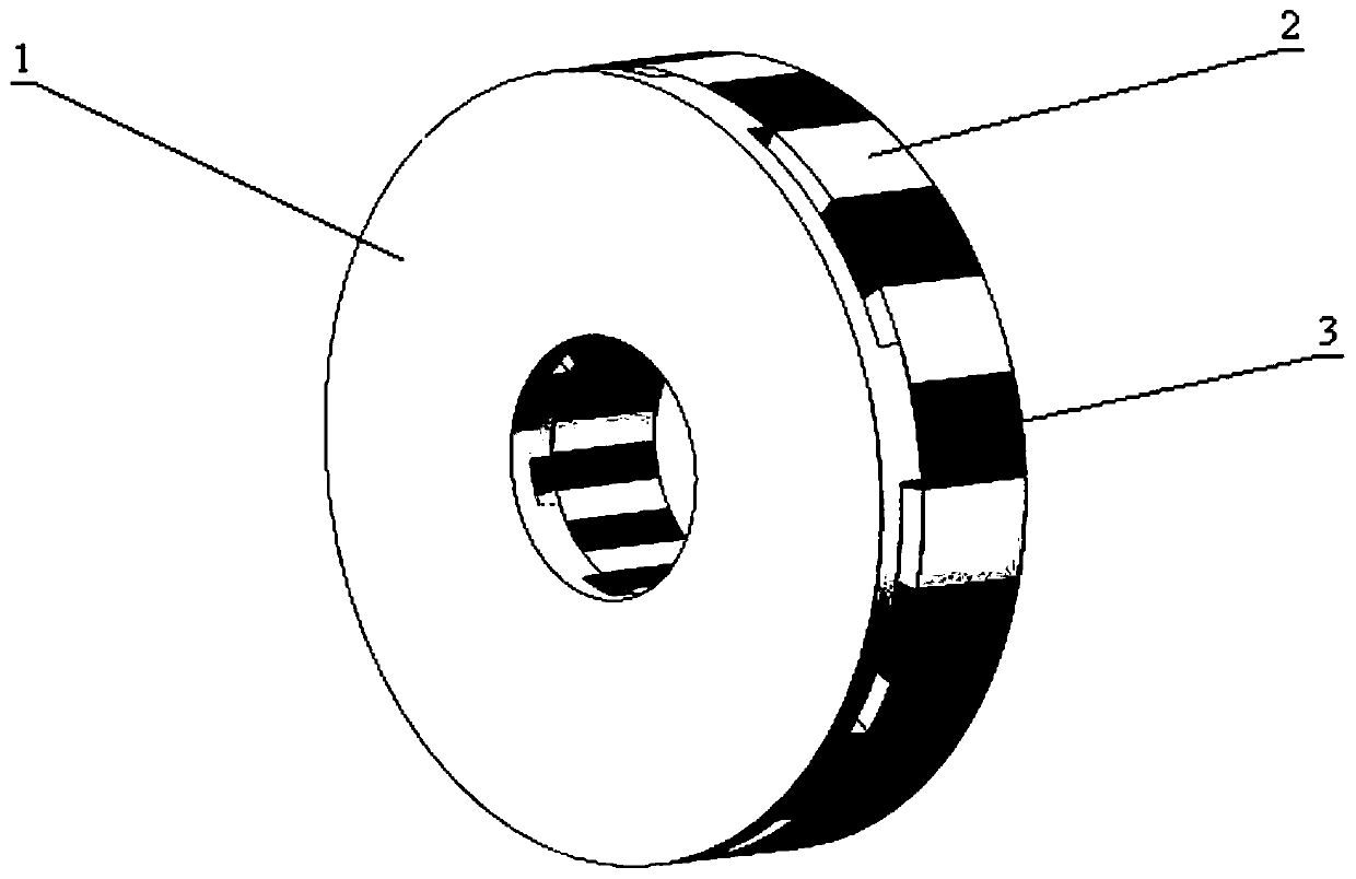
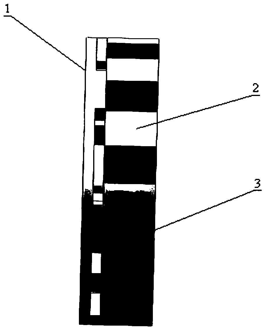
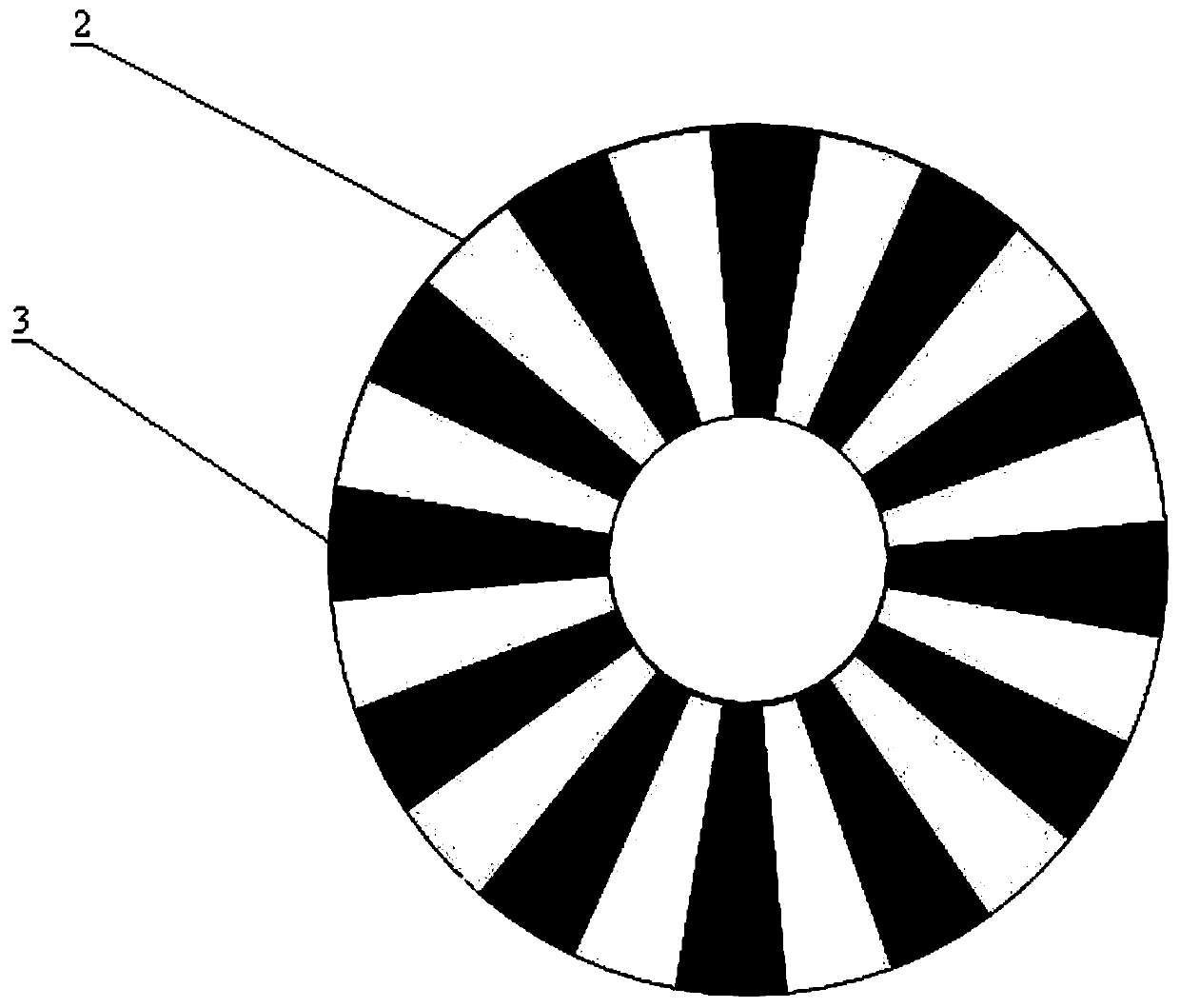
[0071] In this embodiment, the axial magnetic flux switching type transverse flux permanent magnet motor is composed of a plurality of single-phase motor modules, and adjacent single-phase motor modules are offset by a specific angle in the radial direction. Each single-phase motor module has a single-stator and single-rotor structure (see figure 1 ). It includes rotor 1, M special-shaped stator cores 2, M special-shaped permanent magnets 3 and ring-shaped armature windings 6; M special-shaped stator cores and M special-shaped permanent magnets are arranged alternately along the circumferential direction to form a complete ring shape. There are stator ring grooves, the number of special-shaped stator cores and special-shaped permanent magnets is equal, and the number is an even number (see Figure 4 ), the specific shape of the special-shaped stator core and the special-shaped permanent magnet is a U-shaped structure in the present embodiment (see Figure 17 , Figure 18), ...


PUM


Abstract

The invention relates to a transverse flux permanent magnet motor of an axial magnetic field flux switching type, and the motor comprises a plurality of single-phase motor modules, wherein the plurality of single-phase motor modules adopt coaxial radial nesting and / or coaxial axial combination, and the single-phase motor modules of different phases are mutually staggered by electrical angles; eachsingle-phase motor module is of a single-stator single-rotor structure or a single-stator double-rotor structure or a double-stator single-rotor structure; each single-phase motor module comprises aspecial-shaped stator iron core, a special-shaped permanent magnet, a rotor and an armature winding; the M special-shaped stator cores and the M special-shaped permanent magnets are alternately arranged in the circumferential direction to form a stator with a magnetic flux switching type circular ring structure, an annular groove is formed in the circular ring structure, and an armature winding isinstalled in the annular groove; the rotor is of an axial magnetic field disc type structure, and each rotor comprises a rotor yoke with a through hole and a rotor salient pole. The permanent magnetof the motor is arranged on the stator of the motor, and meanwhile, an axial magnetic flux construction mode is adopted, so that the torque density of the motor is improved.

Description

technical field [0001] The invention relates to an axial magnetic flux switching type transverse flux permanent magnet motor, which belongs to the technical field of permanent magnet motors. Background technique [0002] Transverse flux permanent magnet motor is a new type of motor that has emerged in recent years. Compared with traditional permanent magnet motors, it has outstanding advantages such as compact structure, high torque density, and good low-speed performance. Moreover, each phase of the stator of this motor is independent of each other, can be controlled by phase separation, and has better fault tolerance performance. However, the structure of the traditional transverse flux permanent magnet motor is not perfect. If the existing transverse flux motor needs to increase the torque density or increase the number of motor phases, it needs to connect multiple stators with the same structure coaxially. It is more complex and, due to its long axial length, is only su...

Claims


Application Information

Patent Timeline
IPC IPC(8): H02K16/00H02K1/17H02K1/16H02K1/24
CPCH02K16/00H02K1/17H02K1/165H02K1/24H02K2201/12H02K2213/12
Inventor 刘成成王东阳汪友华
Owner HEBEI UNIV OF TECH
Learn More