Eureka AIR delivers breakthrough ideas for toughest innovation challenges, trusted by R&D personnel around the world.

High-throughput forming device and forming method for additive material

A molding device and high-throughput technology, applied in the direction of additive processing, manufacturing auxiliary devices, improving energy efficiency, etc., can solve problems such as energy waste, reduced printing speed, and insufficient powder quantity, so as to improve production efficiency and reduce environmental pollution. The effect of simple replacement and device structure

Active Publication Date: 2019-07-23
NAT INST CORP OF ADDITIVE MFG XIAN
View PDF7 Cites 8 Cited by
  • Summary
  • Abstract
  • Description
  • Claims
  • Application Information

AI Technical Summary

Problems solved by technology

At present, the powder bed laser melting technology adopts the preset powder method, which has the advantage of stable and controllable excessive element quantity compared with other methods. Therefore, the powder bed laser melting technology has great advantages in the preparation of high-throughput materials, but due to the powder bed Laser melting technology adopts the method of presetting powder, which leads to only a certain amount of powder can be prefabricated at a time to prepare a sample layer. When multiple sample layers are required, it is necessary to open the powder bed laser melting cavity to refill the powder and replace the powder bed. The printing environment in the laser melting cavity reduces the printing speed, and multiple powder bed laser melting cavity environment replacements are required, resulting in energy waste, and if the amount of powder added at one time is not enough or superimposed manufacturing is required, it is necessary to refill the powder and reset the molding environment atmosphere

Method used


Image

  • High-throughput forming device and forming method for additive material
  • High-throughput forming device and forming method for additive material

Examples


Embodiment Construction

[0022] The present invention is described in further detail below in conjunction with accompanying drawing:

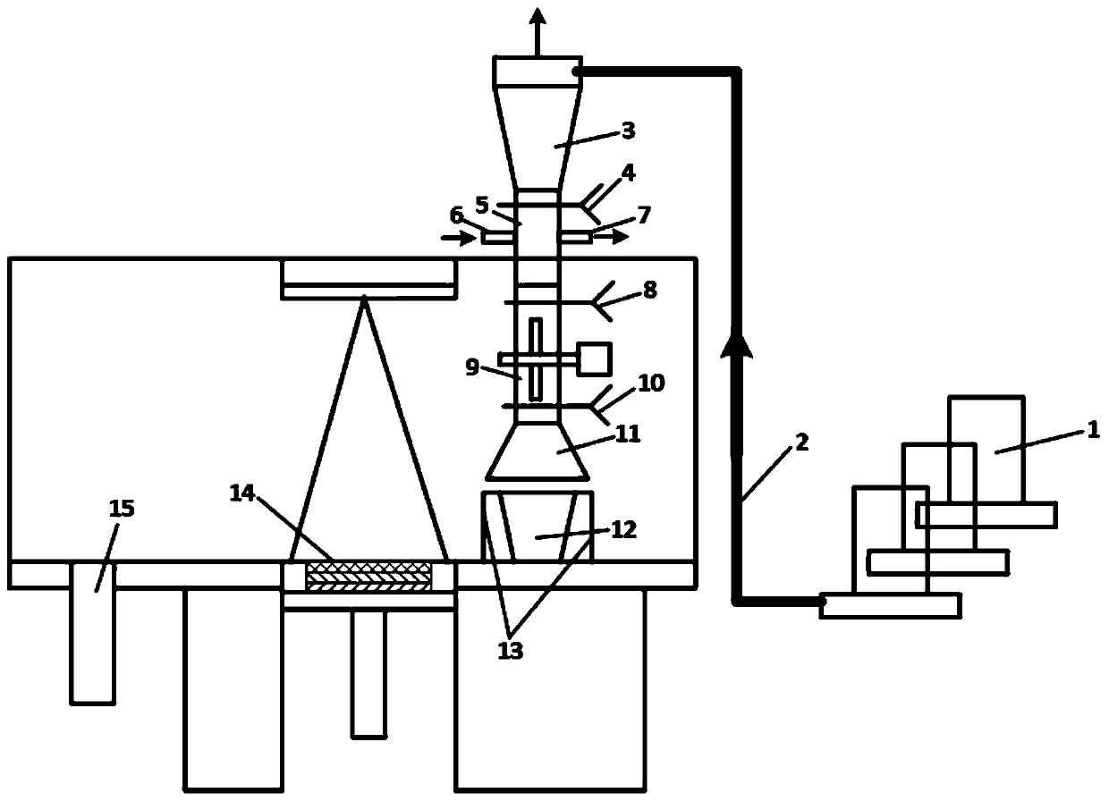
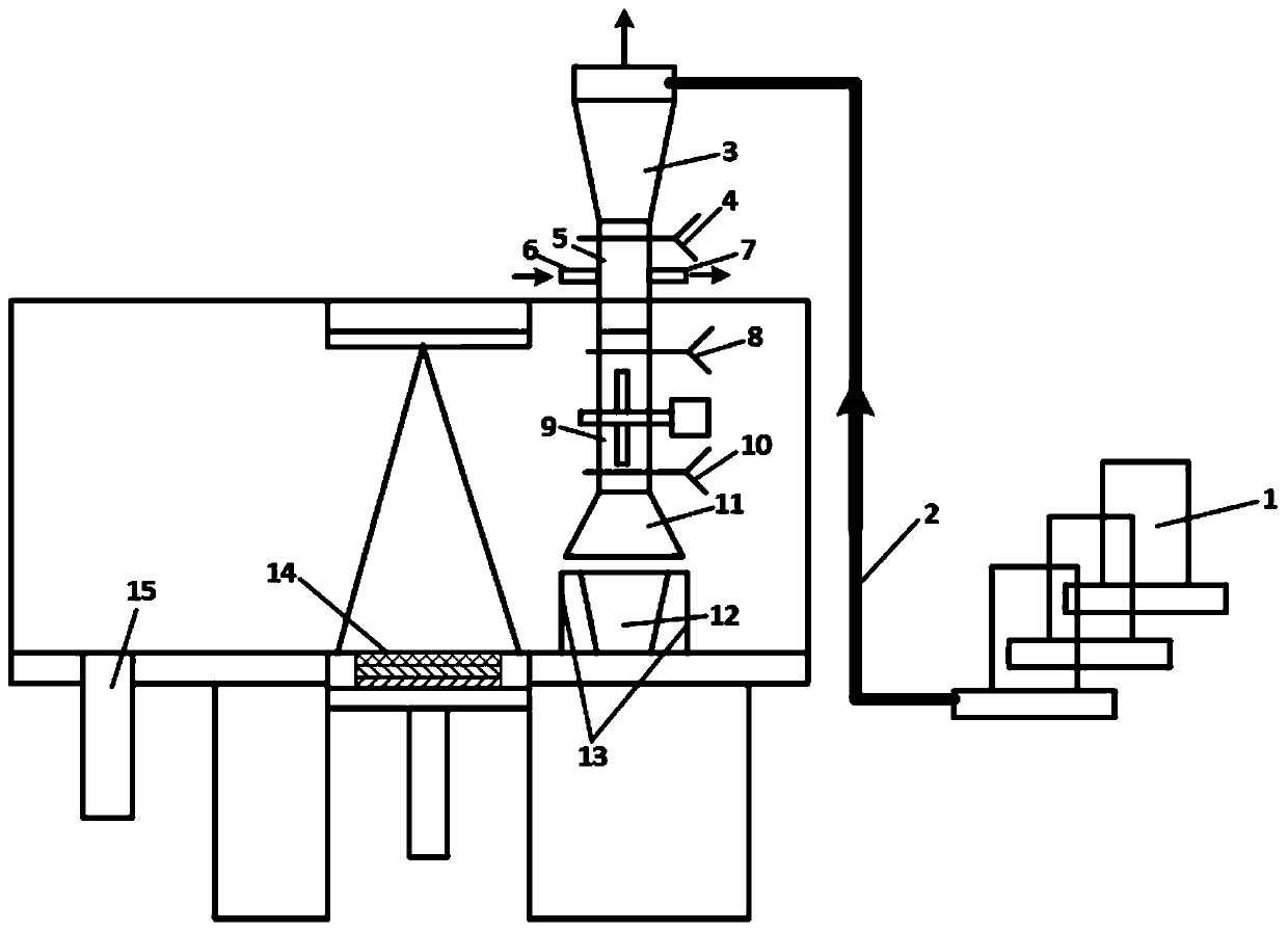
[0023] like figure 1 As shown, a high-throughput molding device for additive materials includes a powder bed laser melting chamber, a powder feeder system, a transition chamber 5 and a powder mixing device 9; the wall of the powder bed laser melting chamber is provided with a transition chamber through hole, The transition cabin 5 is fixed in the through hole of the transition cabin. The upper sealing valve 4 and the lower sealing valve 8 are arranged in the transition cabin 5. A transition cavity is formed between the upper sealing valve 4 and the lower sealing valve 8 in the transition cabin 5. The transition cabin 5 The wall of the transition chamber is provided with an inflatable pipe 6 and an exhaust pipe 7. The upper end of the transition chamber 5 is provided with a gas-powder separation device 3. The gas-powder separation device 3 is connected to the powder fee...


PUM


Abstract

The invention discloses a high-throughput forming device and a forming method for an additive material; by arranging a powder bed laser melting cavity, a powder feeder system, a transition chamber anda powder mixing device as well as forming a transition chamber through hole in the wall of the powder bed laser melting cavity, the transition chamber is fixed in the transition chamber through hole;an upper sealing valve and a lower sealing valve are arranged in the transition chamber to form a transition chamber structure in the transition chamber, and a transition cavity pipe wall of the transition chamber is provided with an inflation pipe and an exhaust pipe, and the powder to be added is subjected to environmental replacement by using the transition cavity structure in the transition chamber so as to avoid replacing the environment in a molding cavity when adding powder again; the effect of screening various materials in one molding is realized; the material preparation efficiencyis doubled; the environmental replacement in the molding cavity is reduced; the device can realize accurate supply of powder at different positions by controlling the supply of powder, and can quicklyreplace different added powder, and metal particles can be molten effectively by a mixing device so that ingredients are uniformly mixed.

Description

technical field [0001] The invention relates to the technical field of high-throughput samples of additive materials, in particular to a high-throughput molding device and molding method for additive materials. Background technique [0002] The development level of materials has always been a symbol of the progress of the times and social civilization. Facing the application environment of rapid industrial technology update and increasingly harsh equipment service environment in the new era, the development of new key materials has become more and more diversified, complex, and Due to the development characteristics of multi-level microstructure, the traditional "trial and error" material development mode not only consumes a lot of time and money, but also is difficult to meet the requirements of material development in the new era due to the limitation of test efficiency. Therefore, there is an urgent need for a Efficient means of material development. However, even in Eur...

Claims


Application Information

Patent Timeline
Patent Type & Authority Applications(China)
IPC IPC(8): B22F3/105B29C64/135B29C64/321B29C64/357B29C64/314B29C64/364B33Y40/00
CPCB29C64/135B29C64/321B29C64/357B29C64/314B29C64/364B33Y40/00B22F10/00B22F10/32B22F10/73B22F10/28B22F12/58B22F12/50Y02P10/25
Inventor 王博文张丽娟卢秉恒陈祯张树哲邹亚桐罗鹏
Owner NAT INST CORP OF ADDITIVE MFG XIAN
Why Eureka
Eureka Blog
Learn More