Steel ball and strong magnet compound type sealing device used for sintering machine

A sealing device and strong magnet technology, applied in the furnace type, furnace, charging processing type, etc., can solve the problems of unsatisfactory use effect, increase production cost of enterprises, harsh environment of sintering site, etc., to ensure long-term stable operation, Extend equipment life and improve system air leakage

Active Publication Date: 2019-07-23
YANSHAN UNIV
View PDF6 Cites 7 Cited by
  • Summary
  • Abstract
  • Description
  • Claims
  • Application Information

AI Technical Summary

Problems solved by technology

[0004] There are many types of sealing devices at the head and tail of the current sintering machine, such as connecting rod type, spring type, flexible seal, magnetized sealing device, etc., but because the sealing device is under the conditions of high temperature, negative pressure, friction and wear, etc., the environment of the sintering site is harsh. After a certain working time of the sealing device, there will usually be damage to the sealing cover, inflexible operation of the device, and increased air leakage rate, etc., and the use effect cannot satisfy the user
[0005] The current trolley seal of the current sintering machine mainly adopts the slideway sealing device. This structure can effectively solve the air leakage problem on both sides of the slideway, but there are still gaps at the end faces of the slideways of adjacent trolleys. Due to the small structure at this place, usually However, there are dozens or even hundreds of slideway end surface contact positions in the sintering exhaust section, and the total amount is considerable. If it is not treated, it will not only waste the effective air volume of the system, but also increase energy consumption. increase the production cost of the enterprise

Method used


Image

  • Steel ball and strong magnet compound type sealing device used for sintering machine
  • Steel ball and strong magnet compound type sealing device used for sintering machine
  • Steel ball and strong magnet compound type sealing device used for sintering machine

Examples


Embodiment Construction

[0024] The following will clearly and completely describe the technical solutions in the embodiments of the present invention with reference to the accompanying drawings in the embodiments of the present invention. Obviously, the described embodiments are only some, not all, embodiments of the present invention. Based on the embodiments of the present invention, all other embodiments obtained by persons of ordinary skill in the art without making creative efforts belong to the protection scope of the present invention.

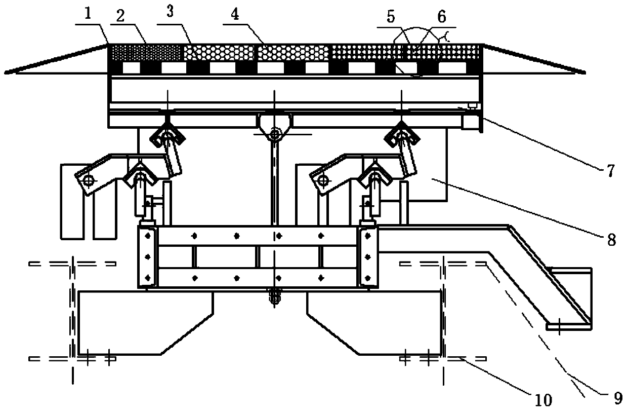
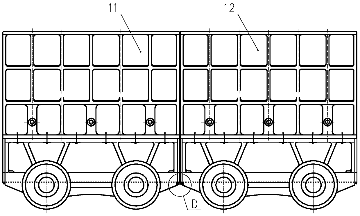
[0025] Such as Figure 1~6 As shown, the steel ball and strong magnet composite head and tail sealing device for sintering machine of the present invention includes two parts: the steel ball and strong magnet composite head and tail sealing device and the trolley slide end face sealing device.

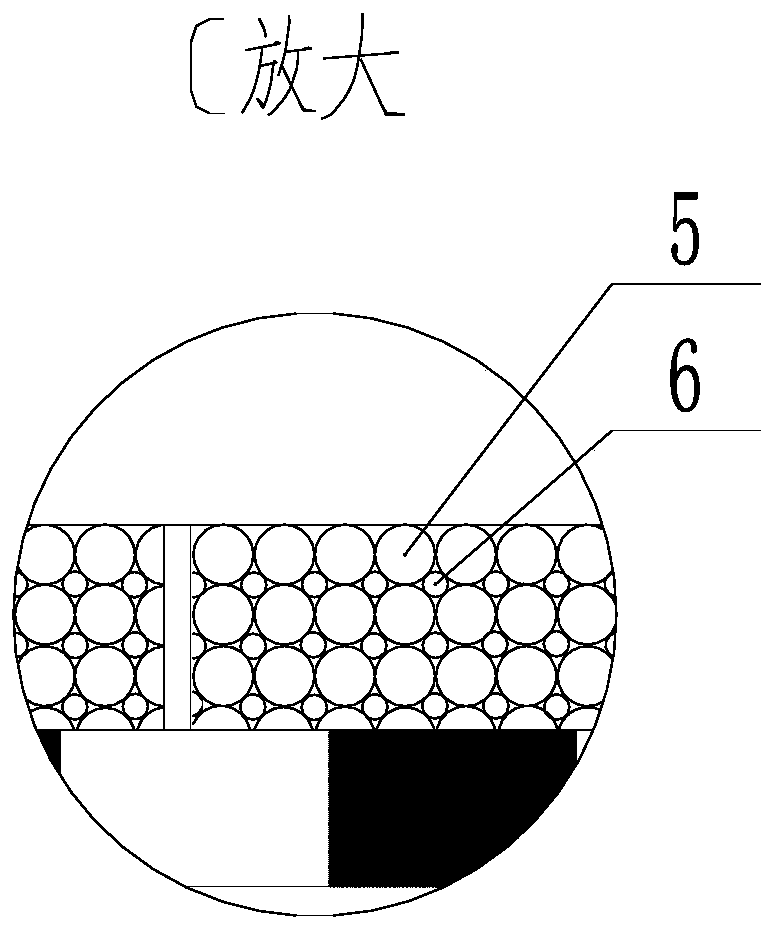
[0026] The steel ball and strong magnet composite head and tail sealing device includes a sealed mine tank 1, steel balls 2, 4, 5, 6, a high-strength magnet 3, a seali...


PUM


Abstract

The invention relates to a steel ball and strong magnet compound type sealing device used for a sintering machine. The steel ball and strong magnet compound type head and tail sealing device comprisesa sealed ore tank, steel balls, high-strength magnets, a sealing beam and an adjustment base. The sealed ore tank is filled with the high-strength magnets and the steel balls of different grain diameters instead of a traditional sealing cover plate, and the rolling sealing effect is achieved. By arranging a magnetic sealing device at the positions of slide way end faces of adjacent trolleys, by means of dependence on the attraction effect of a directionally-magnetized magnet device, iron powder is firmly attracted to the positions of seams of the end portions of slide plates, and then the sealing effect is achieved. Air leakage of a whole sintering system is further reduced, and the ideal ore sintering effect is achieved; and meanwhile electric energy is saved, and high application and popularization value is achieved.

Description

technical field [0001] The invention relates to the field of iron ore sintering equipment, in particular to a steel ball and magnet composite sealing device for belt-type sintering machines used in the metallurgical industry, in particular to a steel ball and strong magnet composite sealing device for sintering machines Head and tail seals. Background technique [0002] In order to improve the sintering conditions of ore powder, it is necessary to ignite and sinter the sintering mixture. Belt sintering machines are widely used in my country to complete the sintering process. The sintering process is a draft production. In order to ensure the air flow through the material layer, it is necessary to install a sealing device on the sintering equipment. At present, the air leakage rate of sintering equipment is generally high. One of the reasons is that there are many air leakage points in the sintering system, such as the head and tail bellows of the sintering machine, the sid...

Claims


Application Information

Patent Timeline
Patent Type & Authority Applications(China)
IPC IPC(8): F27B21/08F27D99/00
CPCF27B21/00F27D99/0073F27M2003/04
Inventor 白明华任素波
Owner YANSHAN UNIV
Why Eureka
Try Eureka