
A fully differential microcapacitance detection chip with strong anti-interference and ultra-low power consumption

A technology with ultra-low power consumption and tiny capacitance, which is applied in the direction of capacitance measurement, measurement device, and measurement of electrical variables, etc. It can solve the problems of being easily affected by noise, temperature sensitivity of the amplifier, and poor anti-interference ability, so as to reduce the aperture time, Effect of canceling noise and temperature drift, avoiding noise sources

Active Publication Date: 2021-07-30
武汉众行聚谷科技有限公司
View PDF0 Cites 0 Cited by
  • Summary
  • Abstract
  • Description
  • Claims
  • Application Information

AI Technical Summary

Problems solved by technology

The result of the relaxation oscillation circuit is simple. When the capacitance to be measured is below 100pF, the inter-board capacitance often affects the measurement results, and the anti-interference ability is poor. In addition, in the process of measuring tiny capacitance, it is more easily affected by noise, and the test accuracy is also poor. There are big challenges
Both the charge amplification method and the switched capacitor method can suppress the influence of stray capacitance and improve the accuracy, but both of them face two major technical problems: First, the theoretical basis of these two technologies is to complete a capacitor through the switching circuit. Charge and discharge process, so as to measure the charge capacity
Due to the charge-injection effect of the mos tube, the measurement will produce a pF-level error
Both, these two technologies convert the capacitance value into a DC voltage and amplify it for measurement, resulting in the temperature-sensitive zero-point drift problem of the amplifier

Method used


Image

  • A fully differential microcapacitance detection chip with strong anti-interference and ultra-low power consumption
  • A fully differential microcapacitance detection chip with strong anti-interference and ultra-low power consumption
  • A fully differential microcapacitance detection chip with strong anti-interference and ultra-low power consumption

Examples


Embodiment Construction

[0042] The following will clearly and completely describe the technical solutions in the embodiments of the present invention in conjunction with the embodiments of the present invention. Obviously, the described embodiments are only part of the embodiments of the present invention, not all of them. Based on the implementation manners in the present invention, all other implementation manners obtained by persons of ordinary skill in the art without making creative efforts belong to the scope of protection of the present invention.

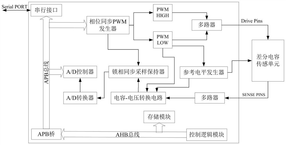
[0043] Such as figure 1 As shown, a fully differential microcapacitance detection chip with strong anti-interference and ultra-low power consumption of the present invention includes a chip body and a differential capacitance sensing unit, and a phase synchronous PWM generator, capacitance-voltage A conversion circuit, a phase-locked synchronous sample-and-hold device, an A / D converter, an A / D controller, a control logic module, a reference level g...


PUM


Abstract

The present invention proposes a fully differential microcapacitance detection chip with strong anti-interference and ultra-low power consumption. By setting a phase-locked synchronous sample holder, the inherent switching noise caused by system design can be suppressed; the fully differential structure reduces the temperature of the amplifier. Conversion noise caused by drift and bias interference; at the same time, the aperture time of the A / D converter is reduced, the accuracy of the A / D converter is improved and the inaccuracy of the conversion time is eliminated; almost all high-frequency harmonics can be filtered component, to obtain a stable DC component, it is not necessary to install an LPF or a phase-sensitive demodulation unit after the capacitor-voltage conversion circuit to obtain a stable DC waveform, thereby avoiding the largest source of systematic noise, cost, power consumption, and transmission Latency has a great advantage.

Description

technical field [0001] The invention relates to the field of micro-capacitance detection, in particular to a micro-capacitance detection chip with strong anti-interference and ultra-low power consumption with a fully differential structure. Background technique [0002] Due to sensor manufacturing process and cost considerations, the capacitance value applied to strain sensing is very small (about 1-10pf), and the capacitance change due to strain force is even smaller (about 0.01-2pf), so extremely precise Detection technology to ensure the accuracy and sensitivity of data. The main idea of ​​high-precision capacitance detection is to convert the capacitance change into a voltage or current signal that is easy to measure, and then detect the change of the signal through the voltage or current signal amplification circuit. Generally, three methods of switching capacitors, relaxation oscillation, and charge amplification are used in the sensor chip. The result of the relaxat...

Claims


Application Information

Patent Timeline
Patent Type & Authority Patents(China)
IPC IPC(8): G01R27/26
CPCG01R27/2605
Inventor 李鹏李向明
Owner 武汉众行聚谷科技有限公司
Learn More