Turning tool changing method based on part surface roughness and power information

A technology of surface roughness and power information, used in computer parts, metal processing equipment, metal processing machinery parts, etc., can solve problems such as multi-energy, prone to errors, increased tool cost, etc., and achieve comprehensive and accurate identification of information. Effect

Active Publication Date: 2019-07-26
TONGJI UNIV
View PDF5 Cites 17 Cited by
  • Summary
  • Abstract
  • Description
  • Claims
  • Application Information

AI Technical Summary

Problems solved by technology

If the time interval between tool changes is too long, it will cause the tool to wear more easily, which will lead to an increase in scrap rate, and it is easy to cause machine failure
The traditional method of tool change is judged by the technician through cutting sound, machining vibration and other methods, but this method requires the workshop staff to have rich experience and is prone to errors, and there are the following problems:
[0003] (1) Setting the threshold of the number of workpieces based on experience is often conservative, and failure to make full use of tool performance will lead to increased tool costs
[0004] (2) In automated production, it is impossible to obtain the status of the tool in real time and adjust the cutting parameters and processing plan in time according to its status, resulting in reduced processing efficiency and processing quality
[0005] (3) Abnormal cutting caused by tool wear causes the machine tool to consume more energy
However, there are the following problems: direct monitoring is suitable for offline detection, and the real-time performance is poor; online optical or image detection devices are difficult to install, and are easily limited by factors such as processing conditions and cutting fluids
The multi-sensor fusion monitoring method can comprehensively monitor the tool status, but there will be redundancy and coupling between signals, and multiple sensors will increase production costs

Method used


Image

  • Turning tool changing method based on part surface roughness and power information
  • Turning tool changing method based on part surface roughness and power information
  • Turning tool changing method based on part surface roughness and power information

Examples


Embodiment

[0068] The present invention will be further described below in conjunction with the content of the present invention and the embodiments described in the accompanying drawings.

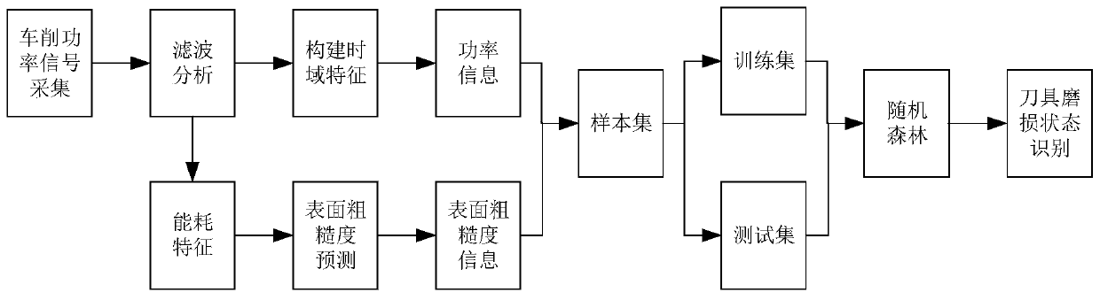
[0069] The present invention proposes a tool changing method for turning machining based on the surface roughness and power information of the part, such as figure 1 shown, including the following steps:

[0070] Step 1, signal acquisition and analysis.

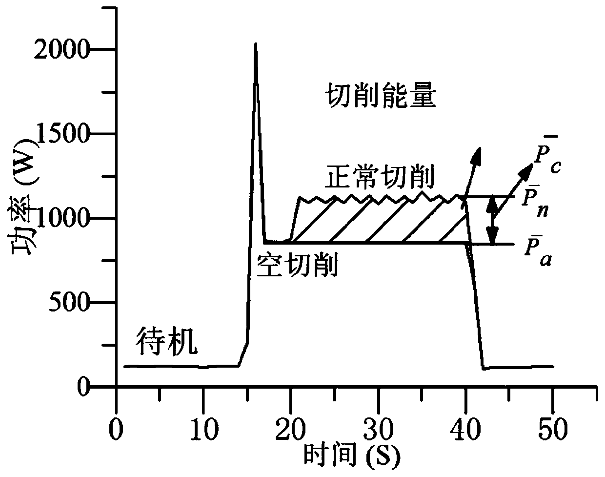
[0071] Signal acquisition and analysis include the collection of power signals and processing parameter information, which refers to the power signal measured by the power sensor in the whole process of processing, including machine tool start-stop, processing and other states, reading the three cutting elements (spindle speed, depth of cut, feed rate) values. Noise and interference exist in the power signal. In order to eliminate the influence of processing waiting time, the power signal from the beginning to the end of cutting of the machine to...


PUM


Abstract

The invention relates to a turning tool changing method based on part surface roughness and power information. The turning tool changing method comprises the following steps that: (1) collecting powersignals and machining parameter information in the turning process through a power sensor; 2) carrying out signal interception on the power signal and carrying out digital filtering by adopting an anti-pulse interference moving average algorithm; 3) constructing a surface roughness prediction model by adopting an improved support vector machine algorithm, and performing surface roughness prediction to obtain predicted surface roughness information; 4) performing feature extraction on the filtered power signal to construct power information; and 5) performing tool wear state classification byadopting a random forest algorithm in combination with the predicted surface roughness information and power information, and completing tool change in the turning process according to a classification result. Compared with the prior art, the method has the advantages of comprehensive information, wide application occasion, feasibility, low cost and the like.

Description

technical field [0001] The invention relates to the field of undo processing, in particular to a tool changing method for turning processing based on part surface roughness and power information. Background technique [0002] Metal cutting tools participate in the cutting process to form the machined surface. Guaranteeing the machining surface accuracy requires high-cutting performance tools. However, as the machining progresses, the tools will gradually wear out. When the wear reaches a certain level, the tools must be replaced to meet the actual processing needs and reduce the economic losses caused by tool wear. But frequent tool changes can cause machine downtime and cause production interruptions and reduced productivity. The downtime caused by tool problems accounts for about 20% of the downtime of the entire machining center. Therefore, a reasonable tool change decision-making method has positive significance for the improvement of actual production and processing q...

Claims


Application Information

Patent Timeline
Patent Type & Authority Applications(China)
IPC IPC(8): G06F17/50G06K9/62B23Q17/09
CPCB23Q17/0957G06F30/20G06F18/2411
Inventor 谢楠陈德基
Owner TONGJI UNIV
Why Eureka
Try Eureka