Rotor magnetic circuit decoupling type high-speed hybrid excitation synchronous motor

A high-speed hybrid, synchronous motor technology, applied to synchronous motors with static armatures and rotating magnets, synchronous machines, synchronous machine parts, etc. Permanent magnet rotor magnetic circuit coupling, increase stator core loss, etc., to achieve the effect of improving electric excitation efficiency, reducing axial length and weight, and improving torque/power density

Active Publication Date: 2019-07-26
NANJING UNIV OF AERONAUTICS & ASTRONAUTICS
View PDF9 Cites 4 Cited by
  • Summary
  • Abstract
  • Description
  • Claims
  • Application Information

AI Technical Summary

Problems solved by technology

[0005] Purpose of the invention: In order to overcome the deficiencies in the prior art, the present invention provides a new rotor magnetic circuit decoupling type hybrid excitation synchronous motor structure to overcome the complex structure of the existing series / parallel hybrid excitation motor, electric excitation and The magnetic circuit coupling of the permanent magnet rotor is serious, and the existing parallel hybrid excitation motor has a large invalid axial length, a large weight of the whole machine, is not suitable for high-speed operation, and the stator core loss will be increased during the field weakening process

Method used


Image

  • Rotor magnetic circuit decoupling type high-speed hybrid excitation synchronous motor
  • Rotor magnetic circuit decoupling type high-speed hybrid excitation synchronous motor
  • Rotor magnetic circuit decoupling type high-speed hybrid excitation synchronous motor

Examples


Embodiment Construction

[0041] The present invention will be further described below in conjunction with the accompanying drawings.

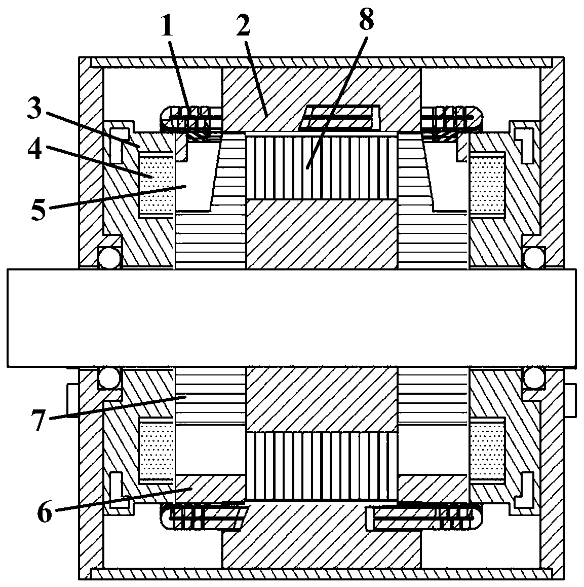
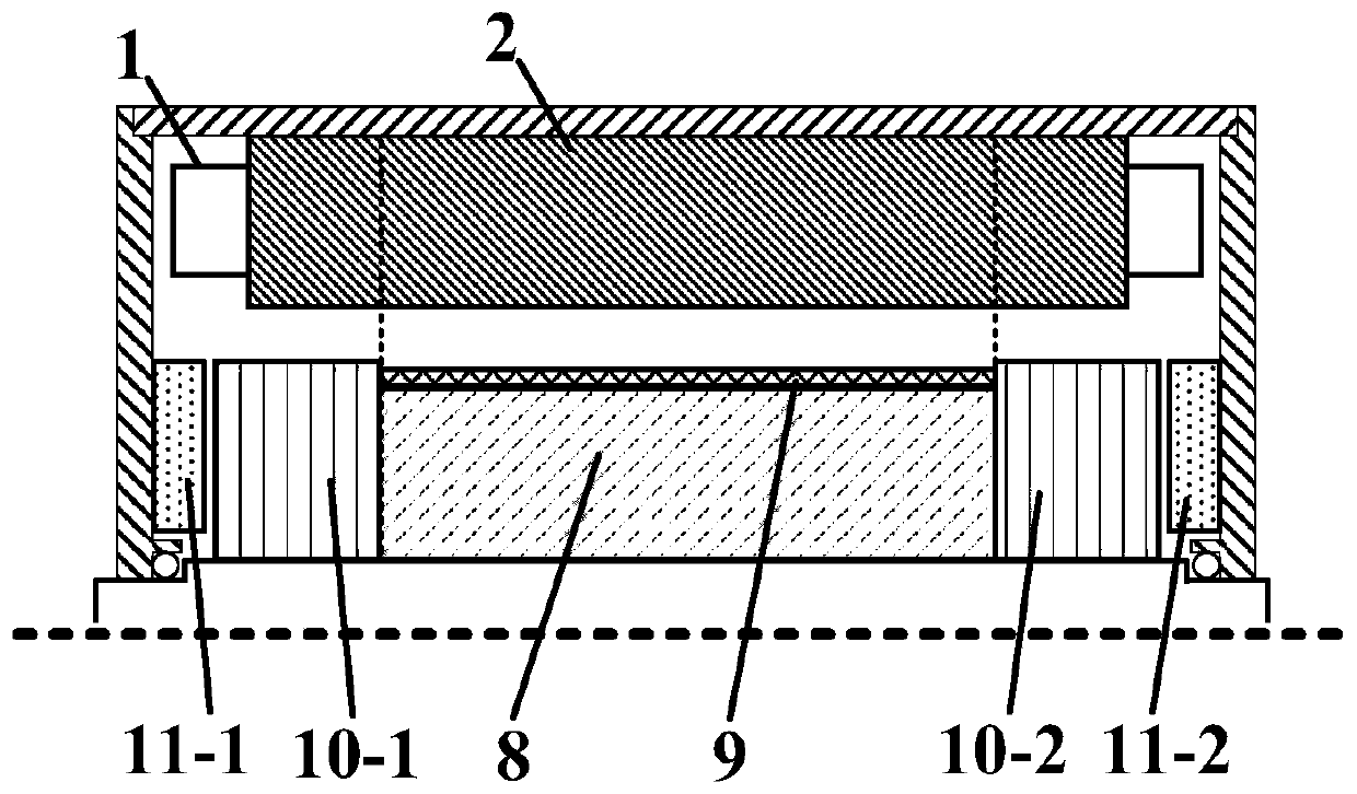
[0042] Such as figure 1 , figure 2 As shown, the present invention provides a rotor magnetic circuit decoupling high-speed hybrid excitation synchronous motor, including a casing and a stator winding 1, a stator core 2, a permanent magnet rotor 8, an electric excitation rotor 10, and an excitation structure arranged in the casing 11 and the rotating shaft; the stator winding 1 is embedded in the slot of the stator core 2; the stator core 2 is fixed on the casing, the stator core material can adopt the traditional punching structure, and the use of soft magnetic composite materials is more conducive to further reducing the core loss in the weak magnetic state ; The permanent magnet rotor 8 is seamlessly assembled with the electric excitation rotor 10-1 and the electric excitation rotor 10-2 on the rotating shaft.

[0043] The physical quantity symbols involved in the...


PUM


Abstract

The invention discloses a rotor magnetic circuit decoupling type high-speed hybrid excitation synchronous motor. The rotor magnetic circuit decoupling type high-speed hybrid excitation synchronous motor comprises a machine shell, a stator, a permanent magnet rotor, an electric excitation rotor, an excitation winding, a magnetic conduction bridge fixed on an end cover and a rotating shaft, whereinthe permanent magnet rotor is composed of magnetic steel, a rotor iron core and a high-strength sheath; a surface-mounted structure is adopted, and the structural strength of the permanent magnet rotor can be effectively improved through the high-strength sheath; and the electric excitation rotor is composed of a rotor N pole, an S pole iron core and a high-strength support, and the structural strength of the electric excitation rotor can be effectively improved by the high-strength support. The lengths of two sections of main air gaps formed between the side of the permanent magnet rotor andthe stator core and between the side of the electric excitation rotor and the stator core are different, so that low permanent magnet eddy current loss and the high electric excitation efficiency canbe realized simultaneously. The rotor permanent magnet magnetic circuit of the hybrid excitation synchronous motor is decoupled from an electric excitation magnetic circuit, the air gap magnetic fieldadjustment range is wide, the eddy current loss of the rotor magnetic steel is low, the electric excitation efficiency is high, the structural strength of the permanent magnet and electric excitationcombined rotor is high, and the motor is suitable for high-speed occasions needing magnetism regulation operation.

Description

technical field [0001] The invention relates to the field of synchronous motors, in particular to a rotor magnetic circuit decoupling high-speed hybrid excitation synchronous motor. Background technique [0002] The excitation source of the hybrid excitation motor is provided by the permanent magnet and the excitation winding. The permanent magnet excitation can effectively improve the torque / power density and operating efficiency of the motor. Torque / power density, high efficiency and wide-ranging operation capability have broad application prospects in wind power generation, aircraft and vehicle power supplies and other independent power generation fields and drive fields. According to the interaction relationship between the permanent magnet magnetic potential and the electric excitation magnetic potential, the hybrid excitation motor can be divided into three structures: magnetic potential series, parallel and parallel. [0003] The permanent magnet magnetic potential o...

Claims


Application Information

Patent Timeline
IPC IPC(8): H02K21/14H02K21/02
CPCH02K21/025H02K21/14
Inventor 张卓然刘业王晨高华敏
Owner NANJING UNIV OF AERONAUTICS & ASTRONAUTICS
Why Eureka
Try Eureka