Optical fiber microwave and optical frequency simultaneous transmission device and transmission method

An optical and microwave technology, used in optical fiber transmission, electromagnetic wave transmission systems, transmission systems, etc., can solve the problems of increasing system complexity, unable to achieve simultaneous transmission of optical frequency and microwave frequency, etc., to achieve high reliability and simple system structure. Effect

Active Publication Date: 2019-07-26
SHANGHAI JIAO TONG UNIV
View PDF3 Cites 20 Cited by
  • Summary
  • Abstract
  • Description
  • Claims
  • Application Information

AI Technical Summary

Problems solved by technology

[0003] At present, most of the optical frequency and microwave optical frequency transmission based on optical fiber links are separated, and there are few reports that a system can simultaneously transmit optical frequency and microwave frequency
At the same time, the way of sepa...

Method used


Image

  • Optical fiber microwave and optical frequency simultaneous transmission device and transmission method
  • Optical fiber microwave and optical frequency simultaneous transmission device and transmission method
  • Optical fiber microwave and optical frequency simultaneous transmission device and transmission method

Examples


Embodiment Construction

[0033] Below in conjunction with embodiment and accompanying drawing, the present invention will be further described, and present embodiment is carried out on the premise of technical solution of the present invention, has provided detailed implementation mode and and specific work flow, but protection scope of the present invention is not limited to the following the described embodiment.

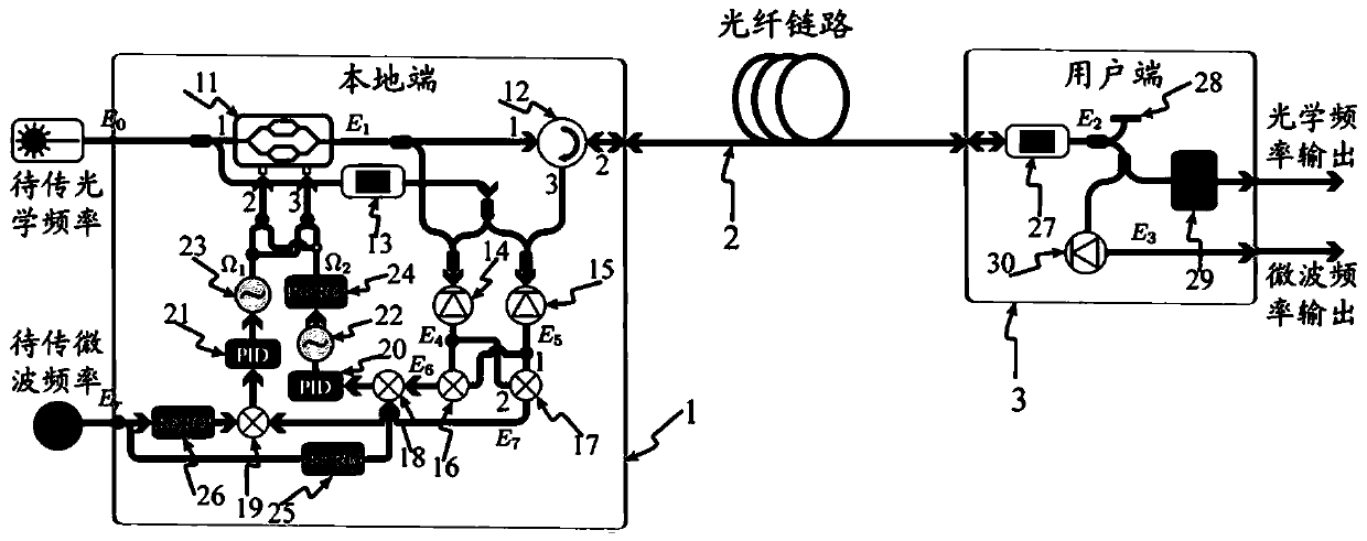
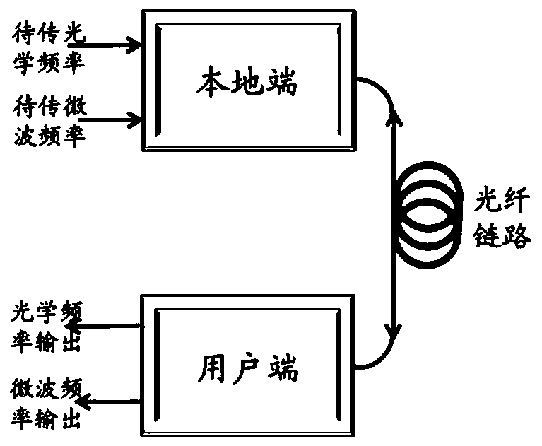
[0034] figure 1 It is a schematic structural diagram of an embodiment of the fiber optic microwave and optical frequency transmission device embodiment of the present invention. In this embodiment, a bidirectional optical amplifier and an optical fiber form an optical fiber link 2, the local end 1 is located at one end of the optical fiber link 2, and the user end 3 is located at the end of the optical fiber link The other end of road 2.

[0035] Optical frequency signal E to be transmitted from local terminal 1 0 Divided into two parts: a part of the optical frequency signal E 0 After...


PUM


Abstract

The invention discloses an optical fiber microwave and optical frequency simultaneous transmission device and transmission method. The optical fiber microwave and optical frequency simultaneous transmission device comprises a local end, an optical fiber link and a user end. Microwave and optical frequency are coupled at the local end through a broadband electro-optical coupling and frequency shifting unit, and THE coupled signals comprise two paths of optical frequency signals and are sent to the user end through the optical fiber link. the user end returns the received signals to the local end again through the same path via the frequency shift unit and the light reflection unit. The phase noise introduced by the optical fiber link is obtained by comparing the signals subjected to electro-optical conversion and frequency mixing processing with the phase frequency discrimination of a microwave signal to be transmitted at the local end, and the dynamic compensation of the phase noise introduced by the optical fiber link is realized by dynamically adjusting the working frequency loaded to the electro-optical coupling and frequency shifting module at the local end. Two paths of optical frequencies with stable phases and microwave signals with stable phases between the two paths of optical frequencies are obtained at the user end, so that simultaneous transmission of microwaves andoptical frequencies is realized. Broadband coupling of microwave and optical frequency and system compensation of phase noise are achieved through the broadband electro-optical coupling and frequencyshift module, integrated optical fiber microwave and optical frequency simultaneous transmission is achieved, and the system is simple in structure and high in reliability.

Description

technical field [0001] The invention relates to optical fiber time and frequency transmission, in particular to an optical fiber microwave and optical frequency simultaneous transmission device and transmission method. Background technique [0002] Time is the one with the highest measurement accuracy among the seven international basic units. In the above, the precise time frequency plays a crucial role. With the rapid development of optical frequency standard technology, it has become a strong contender for the next generation time-frequency reference. Although optical frequency has high frequency transmission stability, the current global commercial frequency standard is still dominated by microwave atomic clocks. Therefore, realizing simultaneous transmission of microwave and optical frequencies has important application value and practical significance. First of all, the development of next-generation time-frequency references based on optical clocks requires high-pr...

Claims


Application Information

Patent Timeline
IPC IPC(8): H04B10/25H04B10/556
CPCH04B10/5561H04B10/5563H04B10/2589H04B10/25891
Inventor 胡亮吴龟灵陈建平
Owner SHANGHAI JIAO TONG UNIV
Why Eureka
Try Eureka