Sampling Oscilloscope, Trigger Generation Method, and Sampling Method

A technology of oscilloscope and sampler, which is applied in the direction of instruments, digital variable display, generation/distribution of signals, etc.

Active Publication Date: 2021-09-07
ANRITSU CORP
View PDF9 Cites 0 Cited by
  • Summary
  • Abstract
  • Description
  • Claims
  • Application Information

AI Technical Summary

Problems solved by technology

However, in essence, it will not become a complete positive number in the direct digital frequency synthesizer, so it may be further divided by 32 to reduce it to about 1kHz

Method used


Image

  • Sampling Oscilloscope, Trigger Generation Method, and Sampling Method
  • Sampling Oscilloscope, Trigger Generation Method, and Sampling Method
  • Sampling Oscilloscope, Trigger Generation Method, and Sampling Method

Examples


Embodiment Construction

[0025] Hereinafter, modes for implementing the present invention will be described in detail with reference to the drawings.

[0026] [Summary of the present invention]

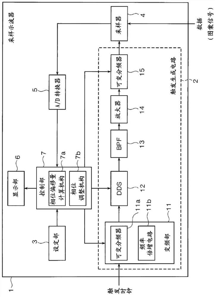
[0027] figure 1 Among them, the precondition is that the clock frequency of the trigger clock synchronized with the data (pattern signal)=Baud Rate. In addition, when a frequency-divided clock is used as a trigger clock, its frequency division ratio is considered as a weight of the variable frequency divider 11a.

[0028] The input frequency DDSInput of DDS12 must be 1.25GHz~2.5GHz, so it is necessary to use the variable frequency divider 11a to divide the frequency. The variable frequency divider 11a becomes a power of 2, so the input frequency DDSInput of DDS12 is expressed as DDSInput=Baud Rate*1 / 2 n .

[0029] Moreover, the output frequency DDSOutput of the DDS12 must be a frequency that can pass through a BPF (Band Pass Filter) 13 . If DDS12 is set to α / 32 frequency division to calculate (α=18~29 po...


PUM


Abstract

The sampling oscilloscope of the present invention includes a trigger generation circuit and a control unit, the trigger generation circuit generates a gate signal for sampling an input pattern signal, and has: a direct digital frequency synthesizer with a phase accumulator to output A frequency output trigger clock input according to the count value of the phase accumulator; a bandpass filter, which limits the passband of the trigger clock output by the direct digital frequency synthesizer; and a variable frequency divider, which passes through the bandpass A filter restricts a passband of a trigger clock for frequency division, the control unit controls the direct digital frequency synthesizer and the trigger generating circuit, and the sampling oscilloscope is characterized in that the control unit uses the The pattern period of the strobe signal is used as a reference to calculate the phase offset of the strobe period of the strobe signal, and to eliminate the calculated phase offset, change the direct digital frequency synthesizer. The count value of the phase accumulator, from which the phase is adjusted.

Description

technical field [0001] The present invention relates to a sampling oscilloscope displaying a waveform based on sampling data obtained by a sampler, a trigger generation method, and a sampling method. Background technique [0002] For example, Patent Document 1 below discloses a technique of sampling a pattern signal by a sampler based on a gate signal generated by a Direct Digital Synthesizer (DDS: DirectDigital Synthesizer) and a programmable counter. [0003] In recent years, due to the popularization of mobile terminals and cloud computing, the amount of data communication has been steadily increasing, and the speed-up of communication speed has also become remarkable. Moreover, the international standard related to high-speed data transmission has changed from the conventional NRZ format to the PAM (Pulse Amplitude Modulation, Pulse Amplitude Modulation) 4 format along with the electrical interface and the optical interface. [0004] And, regarding this PAM4 transmissio...

Claims


Application Information

Patent Timeline
Patent Type & Authority Patents(China)
IPC IPC(8): G01R13/02
CPCG01R13/02G01R13/0254G01R13/0272G06F1/022G06F3/05G06F1/04
Inventor 村上崇
Owner ANRITSU CORP
Why Eureka
Try Eureka