Wireless charging device and wireless charging metal detection device and detection method

A technology of metal detection and wireless charging, which is applied in the direction of circuit devices, battery circuit devices, measuring devices, etc., can solve problems such as the complex composition of harmonic components in oscillating circuits, and achieve the effects of low cost, high recognition efficiency, and simple structure

Active Publication Date: 2019-07-30
SHANGHAI JIAO TONG UNIV
View PDF4 Cites 6 Cited by
  • Summary
  • Abstract
  • Description
  • Claims
  • Application Information

AI Technical Summary

Problems solved by technology

[0004] In the above prior art, the harmonic components in the oscillating circuit are complex. When a metal foreign object is inserted between the normally working wireless charging magnetic couplers, the harmonic components in the oscillating circuit are: (1) Electromagnetic waves radiated by the metal detection coil The electromagnetic wave radiated by the eddy current induced in the metal foreign object is induced in the high-order harmonic part of the oscillating circuit, (2) The electromagnetic wave radiated by the wireless charging coil is induced in the metal foreign object. The eddy current radiated electromagnetic wave is induced in the oscillating circuit The induced high-order harmonic part and (3) the high-order harmonic part induced directly in the oscillation circuit by the electromagnetic wave radiated by the wireless charging coil

Method used


Image

  • Wireless charging device and wireless charging metal detection device and detection method
  • Wireless charging device and wireless charging metal detection device and detection method
  • Wireless charging device and wireless charging metal detection device and detection method

Examples


no. 1 example

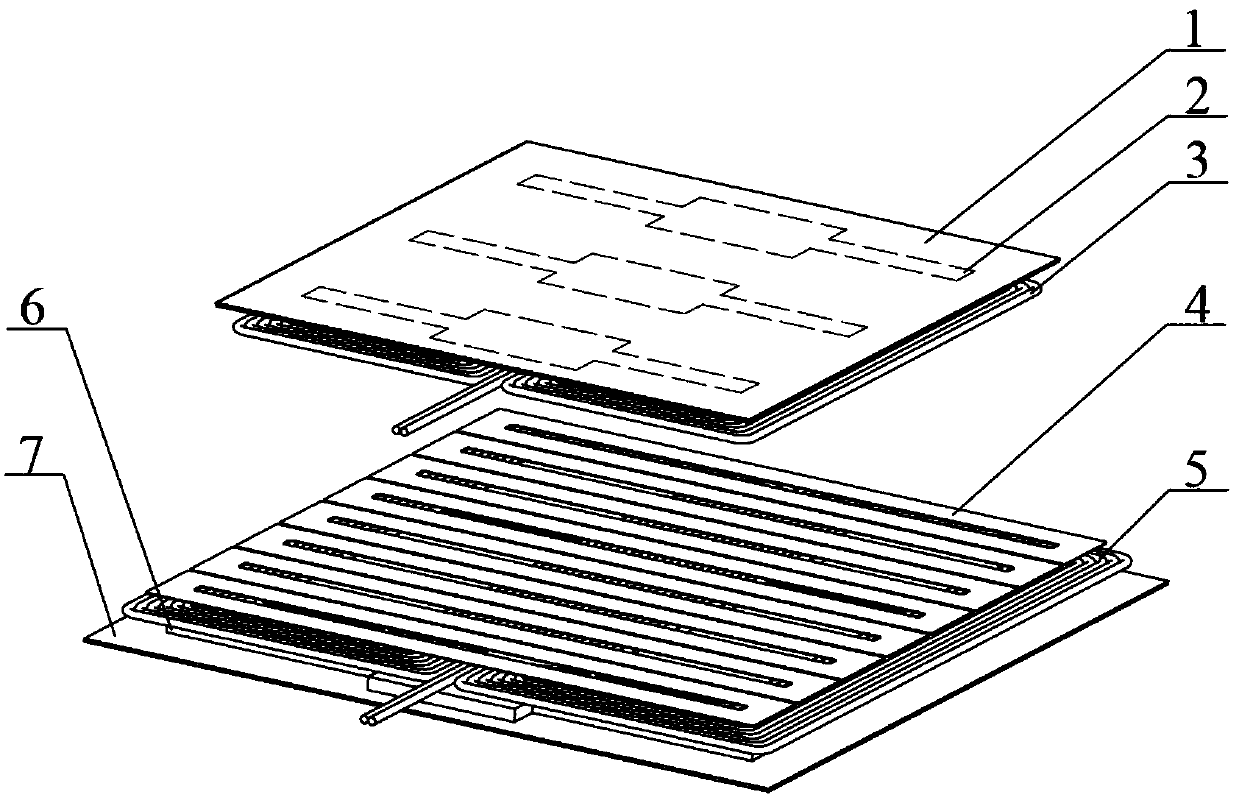
[0113] figure 1 It is a three-dimensional view of the assembly structure of a wireless charging device and a metal detection coil provided by the present invention when the receiving end coil enters the charging area.

[0114] Such as figure 1 As shown, the wireless charging device includes a transmitter coil assembled in the charging area and a receiver coil assembled on the powered device, wherein the transmitter coil includes a second quadrilateral aluminum plate 7, a second strip-shaped iron The second bipolar coil 5 is a second bipolar coil 5 wound in reverse series with the ferrite layer 6 and the Litz wire, and the receiving end coil includes the first quadrilateral aluminum plate 1, the first elongated ferrite layer 2 and the Litz wire reverse A first bipolar coil 3 wound in series. The wireless charging device performs AC excitation on the coil at the transmitting end to induce a high-frequency and high-intensity power electromagnetic field in the charging area, and...

no. 2 example

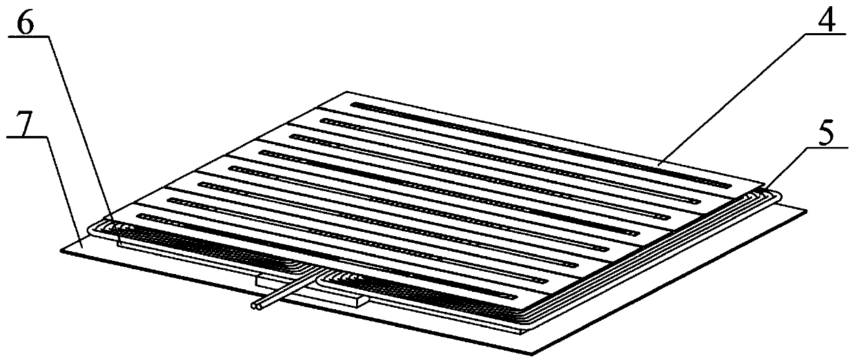
[0125] figure 2 It is a three-dimensional view of the assembly structure of a wireless charging device and a metal detection coil provided by the present invention when the coil at the receiving end does not enter the charging area.

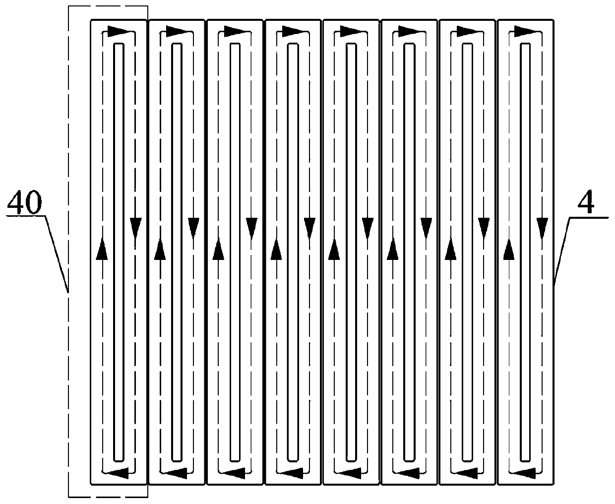
[0126] Such as figure 2As shown, the wireless charging device includes a transmitter coil assembled in the charging area, wherein the transmitter coil includes a second quadrilateral aluminum plate 7, a second elongated ferrite layer 6 and Litz wires wound in reverse series Made of the second bipolar coil 5. The wireless charging device also includes a first metal detection coil 4 arranged in the charging area, its structural diagram and schematic diagram of current direction are shown in image 3 As shown, the first metal detection coil 4 is composed of eight unipolar first single detection coils 40 , and the winding method and current direction of each first single detection coil 40 are exactly the same. The center of the first metal detec...

no. 3 example

[0136] Figure 4 It is a three-dimensional view of the assembly structure of a wireless charging device and a metal detection coil provided by the present invention when the receiving end coil enters the charging area.

[0137] Such as Figure 4 As shown, the wireless charging device includes a transmitter coil assembled in the charging area and a receiver coil assembled on the powered device, wherein the transmitter coil includes a second quadrilateral aluminum plate 7, a second strip-shaped iron The second bipolar coil 5 is a second bipolar coil 5 wound in reverse series with the ferrite layer 6 and the Litz wire, and the receiving end coil includes the first quadrilateral aluminum plate 1, the first elongated ferrite layer 2 and the Litz wire reverse A first bipolar coil 3 wound in series. The wireless charging device performs AC excitation on the coil at the transmitting end to induce a high-frequency and high-intensity power electromagnetic field in the charging area, a...


PUM


Abstract

The invention provides a wireless charging device and a wireless charging metal detection device and detection method. The metal detection device comprises a signal generation circuit, a parallel resonant circuit, a filtering circuit, a peak maintenance circuit, a control circuit and a notification unit, wherein the parallel resonant circuit comprises a metal detection coil, the interference condition of a metal foreign matter can be reflected according to impedance change of the metal detection coil, the signal generation circuit, the parallel resonant circuit, the filtering circuit and the peak maintenance circuit are sequentially connected in series, and the control circuit is connected with the signal generation circuit, the peak maintenance circuit and the notification unit. The metaldetection method comprises the main steps of actively acquiring optimal excitation frequency of the metal detection coil by a mode of frequency sweeping and tuning, sequentially driving a plurality of single detection coils which are not adjacent to each other by a mode of cycle scanning, reading output voltage change of the peak maintenance circuit by the control circuit, and making a response.The metal detection device has the advantages of simple structure, low cost and high identification efficiency.

Description

technical field [0001] The present invention relates to the technical field of high-power wireless charging, in particular to a wireless charging device, a wireless charging metal detection device and a detection method, in particular to a wireless charging metal detection device and a metal detection method based on impedance detection. Background technique [0002] Usually, it is necessary to add metal detection devices for the practical application of wireless charging systems. The high-frequency and high-intensity electromagnetic field generated by the wireless charging magnetic coupler will induce eddy currents in the metal objects placed in it, which will heat them up rapidly and cause dangerous situations. The metal detection device can sensitively detect the intervention of metal foreign objects, cut off the power in time and issue a warning. [0003] For example, the patent document CN104160300B uses a sine wave oscillating current with a single fundamental frequen...

Claims


Application Information

Patent Timeline
Patent Type & Authority Applications(China)
IPC IPC(8): H02J50/60G01N27/00H02J7/00
CPCG01N27/00H02J7/0021H02J7/025H02J7/0047H02J50/60
Inventor 张希张亚蒙张智敏张彬
Owner SHANGHAI JIAO TONG UNIV
Why Eureka
Try Eureka