Lift pin and vacuum treatment device

A lifting pin, non-processing technology, applied in the direction of gaseous chemical plating, coating, electrical components, etc., can solve the problems of poor etching uniformity, plasma unevenness, bad, etc., and achieve the effect of suppressing scars and achieving uniformity

Pending Publication Date: 2019-07-30
ULVAC INC
View PDF12 Cites 0 Cited by
  • Summary
  • Abstract
  • Description
  • Claims
  • Application Information

AI Technical Summary

Problems solved by technology

Therefore, there is a problem that the plasma generated on the surface of the substrate mounted on the substrate mounting surface is not uniform.
Since the plasma is not uniform, the film thickness distribution of the substrate after the film formation or etching is not uniform, or the etching uniformity is poor
As a result, it causes defects in devices including TFT (Thin Film Transistor, thin film transistor) formed on the substrate.
[0010] Although Patent Document 1 discloses a structure for preventing substrate scratches caused by the contact of the lift pins, the structure of the lift pins does not contribute to solving the problem of uneven plasma

Method used


Image

  • Lift pin and vacuum treatment device
  • Lift pin and vacuum treatment device
  • Lift pin and vacuum treatment device

Examples


example 1

[0091] Image 6 It is a cross-sectional view showing main parts of a lift pin structure according to Modification 1 of the embodiment of the present invention. exist Image 6 In , the same reference numerals are assigned to the same components as those in the above-mentioned embodiment, and description thereof will be omitted or simplified.

[0092] This modification 1 is different from the above-mentioned embodiment in that the central member and the peripheral members are an integral body formed of conductive members.

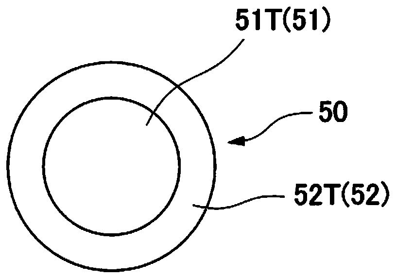
[0093] Specifically, the lift pin 150 has a central region 151 (central member) and a peripheral region 152 (peripheral member), and is an integral body made of aluminum (conductive member). That is, no boundary is formed between the central area 151 and the peripheral area 152 . Although an aluminum oxide film (electrical insulation portion) formed by anodizing aluminum is formed on the first surface 151T of the central region 151 and the second surface 1...

Deformed example 2

[0100] Figure 7 It is a cross-sectional view showing main parts of a lift pin structure according to Modification 2 of the embodiment of the present invention. exist Figure 7 In , the same reference numerals are assigned to the same components as those in the above-mentioned embodiment and Modification 1, and description thereof will be omitted or simplified.

[0101] The second modification example differs from the above-described embodiment in that the surrounding members are conductive members.

[0102] Specifically, the lift pin 250 includes the above-mentioned central member 51 and a surrounding member 252 made of aluminum (conductive member). That is, in Modification 2, the peripheral member 252 made of aluminum is used instead of the peripheral member 52 made of insulating ceramics.

[0103] On the second surface 252T of the peripheral member 252, an aluminum oxide film (electrical insulation portion) formed by anodizing aluminum is formed, but the surface roughnes...

Deformed example 3

[0110] Figure 8 It is a cross-sectional view showing main parts of a lift pin structure according to Modification 3 of the embodiment of the present invention. exist Figure 8 In , the same reference numerals are assigned to the same components as those in the above-mentioned embodiment and Modifications 1 and 2, and description thereof will be omitted or simplified.

[0111] In the above embodiment, if Figure 3A , Figure 3B , Image 6 and Figure 7 As shown, the central member 51 and the peripheral member 52 are adjacent so that the end of the first surface 51T is in contact with the end of the second surface 52T. The present invention is not limited to Figure 3A , Figure 3B , Image 6 and Figure 7 structure shown. For example, if Figure 8 As shown, the second surface 52T and the first surface 51T may also be connected via a step ST. In this case, a concave portion 55 is formed between the upper end 52U of the surrounding member 52 and the first surface 51T...


PUM


Abstract

This lift pin to be in contact with a substrate having a surface to be treated and a surface not to be treated is provided with: a center member, which has a first surface having a first surface roughness and an electric insulating section, and a main body, i.e., a conductive member, and which faces the substrate surface not to be treated; and a peripheral member, which has a second surface havinga second surface roughness that is smaller than the first surface roughness, and an electric insulating section, and which surrounds the periphery of the center member, said peripheral member facingthe substrate surface not to be treated.

Description

technical field [0001] The invention relates to a lifting pin and a vacuum processing device. [0002] This application claims priority based on Patent Application No. 2017-223792 filed in Japan on November 21, 2017, and uses the content here. Background technique [0003] Conventionally, lift pins are known which transfer a substrate between a transfer arm and a substrate holder when transferring a substrate to be processed in a vacuum processing apparatus. The lift pins are provided inside the substrate holder on which the substrate is placed, and the lift pins are protruded from the surface of the substrate holder to transfer the substrate. [0004] As a structure for preventing substrate scratches caused by the contact between the lift pin and the back surface of the substrate, a lift pin in which corners of the lift pin are rounded has been proposed (see Patent Document 1). In addition, as a material constituting the lift pin, ceramics are generally used from the view...

Claims


Application Information

Patent Timeline
IPC IPC(8): H01L21/683H01L21/3065H01L21/31
CPCH01L21/3065H01L21/31H01J37/32082H01J37/32715C23C16/4583C23C16/505H01L21/68742H01J37/32009H01L21/67017H01L21/67259H01L21/683C23C16/458C23C16/50H01J2237/20235H01J2237/3321
Inventor 山本良明神保洋介宮谷武尚江藤谦次阿部洋一
Owner ULVAC INC
Why Eureka
Try Eureka