Vibration bead type maze dust-proof grinding roller device
A vibrating bead and labyrinth technology, applied to engine components, engine sealing, grain handling, etc., can solve problems such as poor dustproof effect
- Summary
- Abstract
- Description
- Claims
- Application Information
AI Technical Summary
Problems solved by technology
Method used
Image

Examples
Embodiment 1
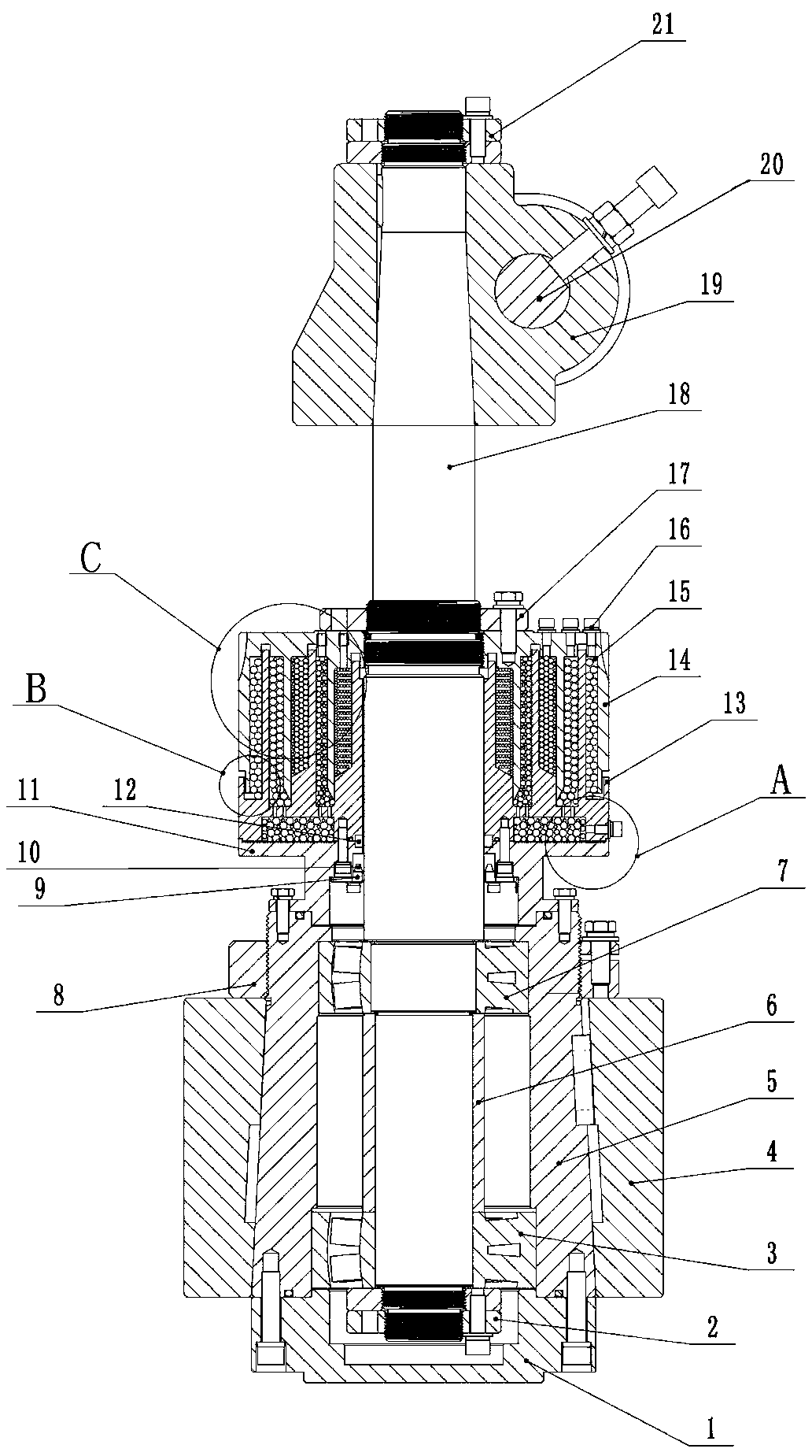
[0036] like figure 1 , figure 2 , image 3 and Figure 4 As shown, a vibrating bead type labyrinth dust-proof grinding roller device, the shaft 18, the support assembly, the dust-proof assembly and the transmission assembly, the support assembly, the dust-proof assembly and the transmission assembly are sequentially sleeved on the shaft from top to bottom, and the existing There are technical differences in that,
[0037] The transmission assembly includes a grinding roller 4, a bearing sleeve 5, a first roller bearing 7, a second roller bearing 3, and a lower gland 1, and the bearing sleeve 5 passes through the first roller bearing 7 and the second roller bearing 3 is sleeved on the shaft 18, and a pressure sleeve 6 is set between the first roller bearing 7 and the second roller bearing 3 to be sleeved on the shaft 18, and the upper end surface of the pressure sleeve 6 withstands the inner ring of the first roller bearing 7 The lower end face, the lower end face of the p...
Embodiment 2
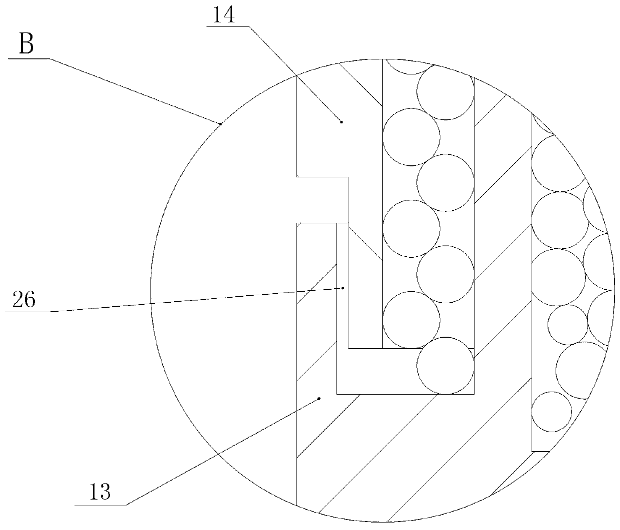
[0053] like Figure 5 , Image 6 , Figure 7 as shown,
[0054] In the labyrinth moving ring 13, the lower end surface and the upper end surface of the swivel are provided with a powder rejection gap 27, and the powder rejection gap 27 communicates with the powder rejection groove 24, so that the dust in the powder rejection groove 24 follows the rotation of the swivel ring 11, and the centrifugal force Under the effect of throwing off powder, the dust in the powder throwing tank 24 is thrown out from the powder throwing gap 27 to the outside.
[0055] All the other parts are identical with embodiment 1.
Embodiment 3
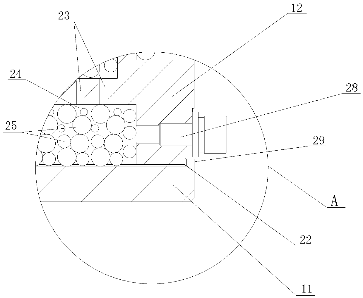
[0057] like Figure 8 , Figure 9 as shown,
[0058] The powder rejection groove 24 is a concave groove located at the upper end of the swivel 11, and no vibration beads 25 are added in the powder rejection groove 24.
[0059] Described swivel 11, outer circle side is provided with air hole 28, and air hole 28 is communicated with powder throwing tank 24, when being convenient to shut down maintenance and repair, blows out the dust settled in the powder throwing tank 24 with air.
[0060] The swivel 11 is a sedimentation ring. The sedimentation ring is formed by round steel through lathe, milling machine, drilling machine, etc. The upper part of the inner circular surface of the sedimentary ring is provided with a positioning ring 13 installation position, and the lower part of the inner circular surface is provided with a reverse flow ring 10 installation position. , the lower end surface of the inner circle is provided with evenly distributed locking through holes connecte...
PUM
 Abstract
Description
Claims
Application Information
 - R&D Engineer
- R&D Manager
- IP Professional
- Industry Leading Data Capabilities
- Powerful AI technology
- Patent DNA Extraction
Browse by: Latest US Patents, China's latest patents, Technical Efficacy Thesaurus, Application Domain, Technology Topic.
© 2024 PatSnap. All rights reserved.Legal|Privacy policy|Modern Slavery Act Transparency Statement|Sitemap