Incineration equipment for coking industry

An equipment and industry technology, applied in the field of incineration equipment, can solve the problems of wasted energy consumption cost, high investment cost, difficult to control the temperature of incineration equipment, etc.

Inactive Publication Date: 2019-08-02
吴起英
View PDF4 Cites 1 Cited by
  • Summary
  • Abstract
  • Description
  • Claims
  • Application Information

AI Technical Summary

Problems solved by technology

In recent years, regenerative incinerator (RTO) has become the choice of more and more coking and refining industries to treat waste gas, especially high-concentration gas source exhaust gas. However, due to the high investment cost of regenerative incinerator, it is difficult to control the incineration equipment. High temp

Method used


Image

  • Incineration equipment for coking industry

Examples


Embodiment 1

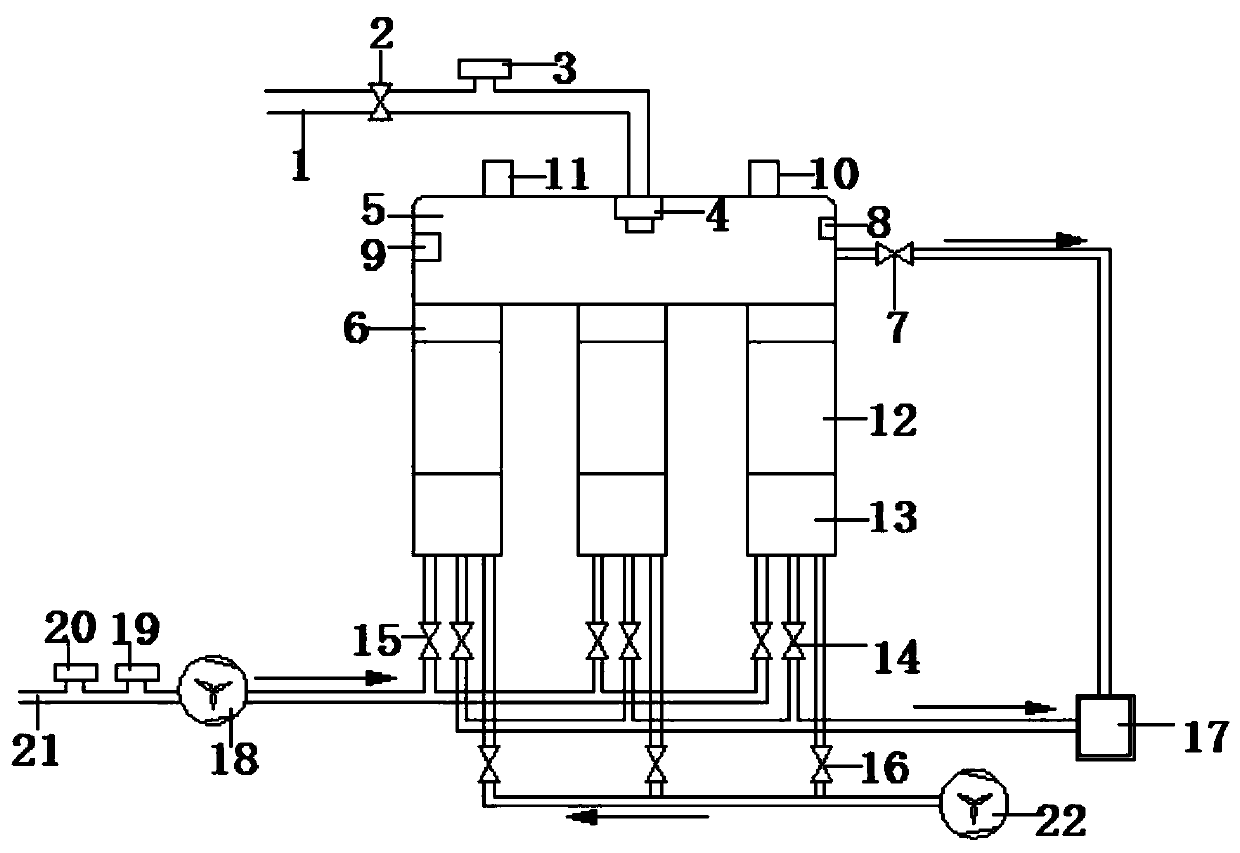
[0011] Such as figure 1 The shown incineration equipment for the coking industry includes a gas inlet pipeline 1, the gas inlet pipeline 1 is connected to a gas inlet valve 2, and the gas inlet valve 2 is connected to a gas flow detector 3. The gas flow detector 3 is connected to the burner 4 by pipelines, and the burner 4 is fixed above the combustion chamber 5. The lower end of the combustion chamber 5 is provided with a regenerator 6, and a temperature relief valve 7, a thermocouple 8 and a thermocouple 8 are installed on both sides. A pressure detector 9, the thermocouple 8 is electrically connected to the temperature alarm 10, the pressure detector 9 is electrically connected to the pressure alarm 11, and the temperature alarm 10 and the pressure alarm 11 are fixed on the outside of the combustion chamber 6 A regenerator 12 is fixed inside the regenerator 6, and the underside of the regenerator 12 is connected to a residue collection tank 13, and the inside of the residue...

Embodiment 2

[0013] Such as figure 1 The shown incineration equipment for the coking industry includes a gas inlet pipeline 1, the gas inlet pipeline 1 is connected to a gas inlet valve 2, and the gas inlet valve 2 is connected to a gas flow detector 3. The gas flow detector 3 is connected to the burner 4 by pipelines, and the burner 4 is fixed above the combustion chamber 5. The lower end of the combustion chamber 5 is provided with a regenerator 6, and a temperature relief valve 7, a thermocouple 8 and a thermocouple 8 are installed on both sides. A pressure detector 9, the thermocouple 8 is electrically connected to the temperature alarm 10, the pressure detector 9 is electrically connected to the pressure alarm 11, and the temperature alarm 10 and the pressure alarm 11 are fixed on the outside of the combustion chamber 6 A regenerator 12 is fixed inside the regenerator 6, and the underside of the regenerator 12 is connected to a residue collection tank 13, and the inside of the residue...


PUM


Abstract

The invention discloses incineration equipment for a coking industry. The incineration equipment comprises a gas inlet pipeline, the gas inlet pipeline is sequentially connected with a fuel gas inletvalve, a fuel gas flow detector and a combustor, the combustor is fixed above a combustion chamber, the lower end of the combustion chamber is provided with a heat storage chamber, the two sides of the combustion chamber are provided with a temperature relief valve, a thermocouple and a pressure intensity detector, the thermocouple and the pressure intensity detector are respectively connected with a temperature alarm and a pressure intensity alarm, a heat accumulator and a residue collecting tank are arranged in the heat storage chamber, the residue collecting tank is provided with an air outlet valve, an exhaust gas inlet valve and a blowing valve, the temperature relief valve and the air outlet valve are connected with a high-temperature mixing tank, the waste gas inlet valve is sequentially connected with a RTO main fan, a waste gas concentration detector and an air access device, the air access device is connected with a waste gas inlet pipeline, and the blowing valve is connectedwith a blower. According to the equipment, the temperature of the incinerating equipment can be controlled, the gas explosion phenomenon caused by VOC in the waste gas can be avoided, and the VOC inthe waste gas can be efficiently removed.

Description

technical field [0001] The invention relates to the technical field of waste gas treatment, in particular to an incineration equipment used in the coking industry. Background technique [0002] At present, the country's requirements for the treatment of organic waste gas are becoming more and more stringent. In recent years, regenerative incinerator (RTO) has become the choice of more and more coking and refining industries to treat waste gas, especially high-concentration gas source exhaust gas. However, due to the high investment cost of regenerative incinerator, it is difficult to control the incineration equipment. High temperature and high concentration of VOC can easily lead to gas explosion. At the same time, the efficient removal of VOC in the exhaust gas and the efficient recovery of the heat released by the oxidation of the exhaust gas waste a lot of energy consumption costs, resulting in hidden dangers and many additional economic losses. Contents of the inventi...

Claims


Application Information

Patent Timeline
IPC IPC(8): F23G7/06F23G5/44F23G5/50
CPCF23G5/44F23G5/50F23G7/06
Inventor 吴起英
Owner 吴起英
Why Eureka
Try Eureka