
A kind of total impedance measuring circuit and measuring device

A technology of measuring devices and measuring circuits, which is applied in the direction of impedance measurement, measuring devices, and measuring electrical variables, etc., can solve the problems of inability to achieve real-time signal processing, cannot guarantee the real-time performance of impedance measurement circuits, and real-time measurement depends on other problems, so as to improve the measurement Accuracy, noise reduction, and error elimination effects

Active Publication Date: 2020-11-03
INST OF COMPUTING TECH CHINESE ACAD OF SCI
View PDF6 Cites 0 Cited by
  • Summary
  • Abstract
  • Description
  • Claims
  • Application Information

AI Technical Summary

Problems solved by technology

However, the impedance measurement circuit has the following problems: 1) whether it can support real-time measurement depends on whether the excitation signal frequency is known accurately; 2) the impedance measurement accuracy will be affected by the performance parameters of the components in the circuit drifting with temperature or time, so Need for drift compensation
Although the analog signal acquisition of this method adopts a dual-channel parallel design, the essence of the seven-parameter sine wave fitting algorithm is based on the improvement of four parameters in the dual-channel measurement scenario (only the noise of the two channels is considered for the overall fitting calculation) , iterative calculation is still required, real-time signal processing cannot be achieved, and the overall measurement time has not been shortened
[0009] None of the above three drift compensation methods can guarantee the real-time measurement of the impedance measurement circuit, and cannot achieve real-time signal processing

Method used


Image

  • A kind of total impedance measuring circuit and measuring device
  • A kind of total impedance measuring circuit and measuring device
  • A kind of total impedance measuring circuit and measuring device

Examples


Embodiment Construction

[0071] The present invention will be further described in detail below in conjunction with the embodiments and the accompanying drawings, but the embodiments of the present invention are not limited thereto.

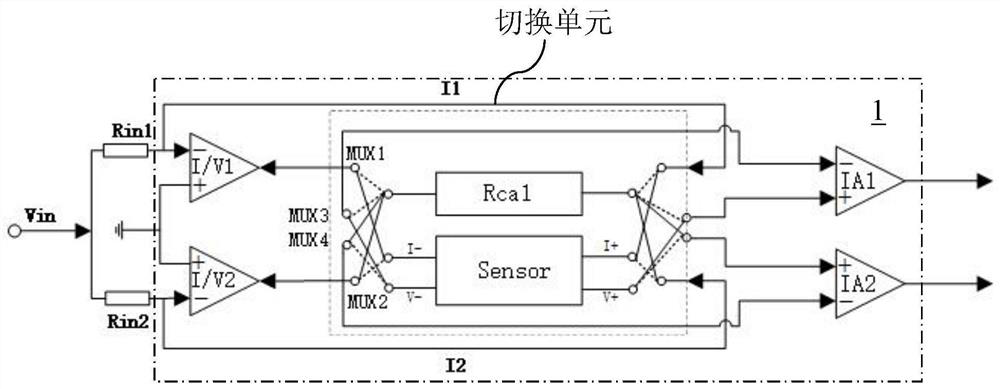
[0072] The total impedance measuring device of the present invention measures the response voltages from the sensor and the reference resistor alternately through parallel dual channels, and the corresponding three-parameter sine wave fitting of each channel, and finally can Significantly reduce or even eliminate the error caused by the performance parameter drift of the components in the circuit to the total impedance measurement, that is, to achieve the purpose of drift compensation.

[0073] A specific embodiment of the total impedance measuring device of the present invention is as figure 1 shown, including:

[0074] Waveform generation unit: generate an excitation signal in the form of a digital sine wave;

[0075] Digital-to-analog conversion unit: convert the ab...


PUM


Abstract

The invention discloses a total impedance measurement circuit and a measurement device. The measurement circuit comprises a first trans-impedance amplifier, a second trans-impedance amplifier, a firstdifferential amplifier, a second differential amplifier, a reference resistor, a sensor and four programmable multiplexers. The current input end of the sensor is used for inputting a current signal,and the voltage output end thereof is used for detecting a response voltage signal; a positive input terminal of the first trans-impedance amplifier and a positive input terminal of the second trans-impedance amplifier are grounded; and the four programmable multiplexers can allow the circuit to be switched in two forms. Through an alternate measurement mode, the waveforms of the measured sensorresponse voltage and the reference resistor response voltage both contain noise information of two channels, thereby ensuring that the noise contained in both waveforms is consistent; and through a three-parameter sine wave fitting algorithm of each channel, noise is reduced synchronously and accurate amplitude and phase estimate values can be obtained respectively, so that measurement accuracy ofthe circuit can be further improved.

Description

technical field [0001] The invention belongs to the technical field of impedance measurement, and in particular relates to a total impedance measurement circuit and a measurement device. Background technique [0002] Conductivity, temperature, and depth sensors (abbreviated as CTD or temperature, salt and depth sensors) are the most basic and important sensors for monitoring the water environment. It not only directly provides conductivity, temperature and pressure parameters, but also can be used to calculate salinity parameters and depth parameters. These parameters are essential for conducting various watershed studies. Taking marine research as an example, these parameters can not only be used to monitor the flow, circulation, and climate change process of seawater, but also provide background physical parameters for the study of biogeochemistry and marine ecosystems. In the study of global climate issues and monitoring of marine ecological environment etc. are of grea...

Claims


Application Information

Patent Timeline
Patent Type & Authority Patents(China)
IPC IPC(8): G01R27/08G01R27/16
CPCG01R27/08G01R27/16
Inventor 曹书乐黄希崔莉
Owner INST OF COMPUTING TECH CHINESE ACAD OF SCI
Learn More