Near-infrared narrow-band filter and manufacturing method thereof

A technology of narrow-band filter and manufacturing method, which is applied in optics, optical components, instruments, etc., can solve problems such as light reflection, and achieve the effects of low reflection energy intensity and low reflection color brightness

Pending Publication Date: 2019-08-02
XINYANG SUNNY OPTICAL CO LTD
View PDF5 Cites 15 Cited by
  • Summary
  • Abstract
  • Description
  • Claims
  • Application Information

AI Technical Summary

Problems solved by technology

[0003] However, when the existing optical filters are used in terminal equipment, there will be problems of light re

Method used


Image

  • Near-infrared narrow-band filter and manufacturing method thereof
  • Near-infrared narrow-band filter and manufacturing method thereof
  • Near-infrared narrow-band filter and manufacturing method thereof

Examples


Embodiment 1

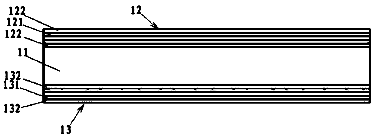
[0062] In the near-infrared narrow-band filter provided in the embodiment of the present application, the second side may be coated with a wide-band pass film system or a long-band pass film system. Table 1a is a film thickness table of a wide band pass film system or a long band pass film system, which reflects the film layer structure of the wide pass film system or long band pass film system of the near-infrared narrow-band filter of the present application. Layers of different thicknesses are alternately plated to form the required film structure. In the structure shown in Table 1a, SiO 2 It is a low refractive index dielectric material, and Si:H is a high refractive index silicon-based material.

[0063] When the first side of the near-infrared narrow-band filter is coated with a bright reflective color narrow-bandpass film system, the structure shown in Table 1b below can be referred to. Table 1b is a film thickness table of the bright reflective color narrow-band pass...

Embodiment 2

[0073] In the near-infrared narrow-band filter provided in the embodiment of the present application, the second side may be coated with a wide-band pass film system or a long-band pass film system. Table 2a is the film layer thickness table of broadband pass film system or long band pass film system. Layers of different thicknesses are alternately plated to form the required film structure. In the structure shown in Table 2a, SiO 2 It is a low refractive index dielectric material, TiO 2 It is a high refractive index material.

[0074] When the first side of the near-infrared narrow-band filter is coated with a bright reflective color narrow-bandpass film system, the structure shown in Table 2b below can be referred to. Table 2b is the film layer thickness table of the bright reflective color narrow band pass film system, which reflects the film layer structure of the bright reflective color narrow band film system of the narrow band pass film system of the near infrared na...

Embodiment 3

[0084] In the near-infrared narrow-band filter provided in the embodiment of the present application, the second side may be coated with a wide-band pass film system or a long-band pass film system. Table 3a is the film layer thickness table of broadband pass film system or long band pass film system. Layers of different thicknesses are alternately plated to form the required film structure. In the structure shown in Table 1a, SiO 2It is a low refractive index dielectric material, and Si:H is a high refractive index silicon-based material.

[0085] When the first side of the near-infrared narrow-band filter is coated with a bright reflective color narrow-bandpass film system, the structure shown in Table 3b below can be referred to. Table 3b is the film layer thickness table of the bright reflective color narrow-band pass film system, which reflects the film layer structure of the bright reflective color narrow-band film system of the narrow-band pass film system of the near...


PUM

PropertyMeasurementUnit
Thicknessaaaaaaaaaa

Abstract

The application provides a near-infrared narrow-band filter and a manufacturing method thereof. The filter comprises a substrate, a narrow-band pass film system arranged at a first side of the substrate, and a broadband pass film system or long-wave pass film system. The broadband pass film system is arranged at a second side, being opposite to the first side, of the substrate; the pass band of the broadband pass film system is wider than that of the narrow-band pass film system; the long-wave pass film system is arranged at the second side, being opposite to the first side, of the substrate;and the pass band of the long-wave pass film system is wider than that of the narrow-band pass film system. The narrow-band pass film system includes a high refractive index layer having the refractive index being larger than 3 within a wavelength range of 780 to 3000nm and a low refractive index layer having the refractive index being less than 3. The reflected color of the near-infrared narrow-band filter meets the following relationships in the CIE xyz coordinate system: x is less than 0.509, y is less than 0.363, and z is less than 50%. Therefore, the near-infrared narrow-band filter having advantages of diversified reflection colors, low reflection energy intensity, and low reflection color brightness can be obtained; and application demands of the under-screen device and vehicle-mounted device in the full screen of the mobile phone can be satisfied.

Description

technical field [0001] The present application relates to the field of optical elements, in particular to a near-infrared narrow-band filter and a manufacturing method. Background technique [0002] With the advancement and development of science and technology, optical filters are widely used in some terminals with face recognition or gesture recognition functions, such as smart phones, car lidar, security access control, smart home, virtual reality / augmented reality / mixed reality , 3D somatosensory games, 3D camera and display and other terminal equipment. [0003] However, when existing optical filters are used in terminal equipment, there will be a problem of light reflection. Therefore, optical filters with better performance are required to be better applied to terminal equipment. Contents of the invention [0004] In view of the technical problems existing in the prior art, the embodiments of the present application provide a near-infrared narrow-band filter and a ...

Claims


Application Information

Patent Timeline
IPC IPC(8): G02B5/28
CPCG02B5/281G02B5/288G02B5/285G02B1/02C23C14/06C23C14/10C23C14/221
Inventor 肖念恭方叶庆丁维红陈策
Owner XINYANG SUNNY OPTICAL CO LTD
Why Eureka
Try Eureka