An automatic analysis system and analysis method for internal leakage of high temperature and high pressure valves in power plants

An automatic analysis system, high temperature and high pressure technology, applied in geometric CAD, design optimization/simulation, computer aided design, etc., can solve problems such as economic losses of enterprises, differences in valve sealing performance, internal leakage, etc., and achieve time saving and temperature measurement range wide effect

Active Publication Date: 2020-03-10
NANJING CHONON ENERGY SAVING TECH
View PDF9 Cites 3 Cited by
  • Summary
  • Abstract
  • Description
  • Claims
  • Application Information

AI Technical Summary

Problems solved by technology

[0003] However, due to the difference in the operating environment of the valve, there are great differences in the sealing performance of the valve, especially for high-temperature and high-pressure valves used in thermal power generation, petroleum and other fields. Due to the long-term operation of the valve, internal leakage will inevitably occur.
[0004] The internal leakage of the valve not only brings economic losses to the enterprise, but also has the safety of the system operation.
The internal leakage of the valve cannot be judged correctly from the appearance. Now most of them adopt the method of ultrasonic detection for analysis and detection. The equipment cannot normally collect effective information data, and the ultrasonic valve internal leakage detection cannot analyze the leakage amount

Method used


Image

  • An automatic analysis system and analysis method for internal leakage of high temperature and high pressure valves in power plants
  • An automatic analysis system and analysis method for internal leakage of high temperature and high pressure valves in power plants
  • An automatic analysis system and analysis method for internal leakage of high temperature and high pressure valves in power plants

Examples


Embodiment Construction

[0027] In the following description, numerous specific details are given in order to provide a more thorough understanding of the present invention. It will be apparent, however, to one skilled in the art that the present invention may be practiced without one or more of these details. In other examples, some technical features known in the art are not described in order to avoid confusion with the present invention.

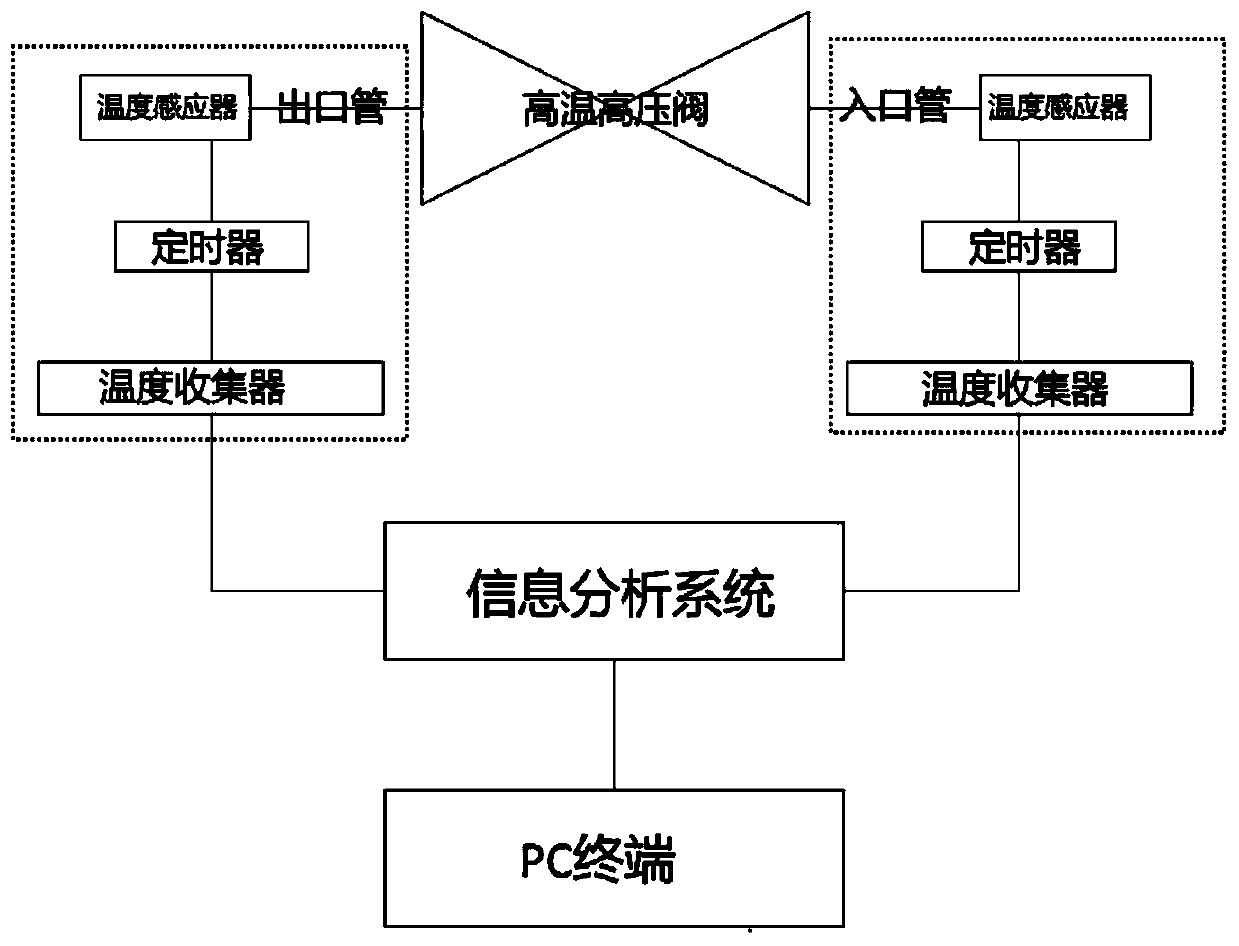
[0028] After the research and analysis of the applicant, the reason for this problem (the internal leakage of the valve brings economic losses to the enterprise, and there is also the safety of the system operation) is that the internal leakage of the valve cannot be judged correctly from the appearance, and most of them now use ultrasonic testing. The sound environment required for ultrasonic testing is relatively high. In thermal power plants where there are many and complicated noise sources, ultrasonic testing equipment cannot normally collect effective info...


PUM


Abstract

The invention discloses an automatic analysis system and analysis method for internal leakage of high temperature and high pressure valves in power plants. The system includes: a temperature collection system, a data analysis system and a terminal system, wherein the temperature collection system includes a high temperature and high pressure valve, which is installed The inlet pipe and outlet pipe on the side are attached to the temperature sensor arranged on the inlet pipe and the outlet pipe, as well as the timer and temperature collector electrically connected with the temperature sensor; the data analysis system includes an electrical connection with the temperature collection system The information analysis system; the terminal system includes a PC terminal remotely connected to the data analysis system. The present invention adopts the method of temperature collection and calculation, and the requirements for the detection environment are not very high, which avoids the shortcomings of ultrasonic valve internal leakage detection. The design of the patch type temperature sensor has a wide range of temperature measurement. Accurately find out whether the valve is leaking, prepare for the company to repair or re-purchase the valve in advance, and save time for the company to repair.

Description

technical field [0001] The invention relates to an automatic valve internal leakage analysis system and method, in particular to a valve internal leakage analysis and detection method suitable for high temperature and high pressure valves in thermal power plants, belonging to a novel valve internal leakage analysis system and method. Background technique [0002] Now the machinery industry is developing more and more rapidly, and valves in the industry are no exception. The valve industry is an important branch of general machinery. As a key equipment for fluid control, it is widely used in industries such as electric power, petroleum, chemical industry, metallurgy, urban construction, and environmental protection. After decades of development, my country's valve manufacturing industry has made great progress. At present, the number of valve enterprises in China ranks first in the world. The production level of valves has also been greatly improved, and the output of valves h...

Claims


Application Information

Patent Timeline
Patent Type & Authority Patents(China)
IPC IPC(8): G06F30/20G06F30/17
CPCG06F30/20G06F30/17
Inventor 周惠
Owner NANJING CHONON ENERGY SAVING TECH
Why Eureka
Try Eureka