Electrochemical water treatment device

A water treatment device and electrochemical technology, applied in the field of electrochemistry, can solve the problems of small processing capacity, difficult engineering, and inability to enlarge the volume, and achieve the effects of solving hydraulic retention time, reducing energy consumption, and good treatment effect

Active Publication Date: 2019-08-06
DALIAN UNIV OF TECH
View PDF3 Cites 4 Cited by
  • Summary
  • Abstract
  • Description
  • Claims
  • Application Information

AI Technical Summary

Problems solved by technology

An electrochemical water treatment device of the present invention is based on electrochemistry, which cleverly combines electrodes, electrolytes, water inlets and casings to achieve the goals of degrading pollutants and treating waste water; and solves the problem of Some reactors cannot be enlarged, and the processing capacity is too small to be engineered

Method used


Image

  • Electrochemical water treatment device
  • Electrochemical water treatment device
  • Electrochemical water treatment device

Examples


Embodiment 1

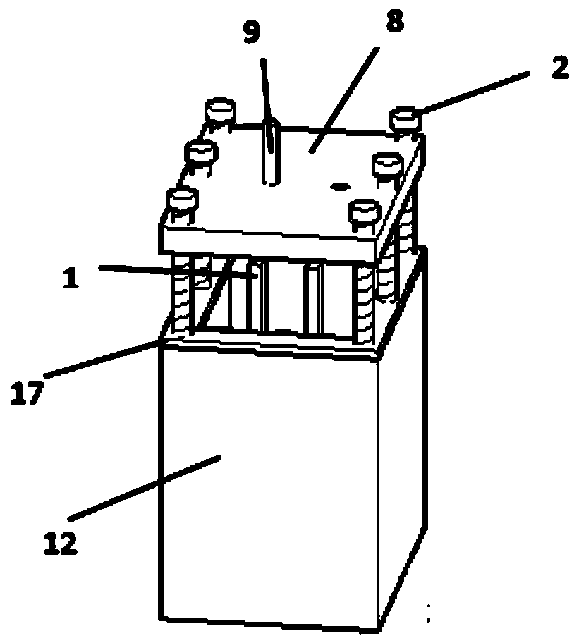
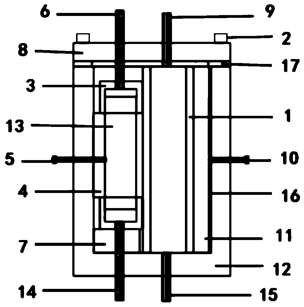
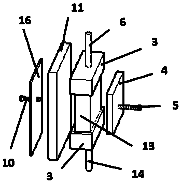
[0020] Such as figure 2 As shown, the electrochemical water treatment device based on the multi-level channel electrode 13 includes a baffle plate 1, a screw 2, a water collection and distribution groove 3, a multi-level channel electrode waterproof insulating pad 4, and a multi-level channel electrode terminal 5 , connecting pipe A6, bearing plate 7, device housing cover 8, connecting pipe B9, counter electrode terminal 10, counter electrode 11, device housing 12, multi-stage channel electrode 13, communicating tube C14, communicating tube D15, counter electrode waterproof insulation Pad 16 and gasket 17. First, install the baffle plate 1 and the load-bearing plate 7 to a suitable position. After tightly wrapping the two ends of the multi-stage channel electrode 13 with the water-collecting distribution groove 3, place it on the load-bearing plate 7 as a whole, and place the multi-stage channel electrode The waterproof insulating pad 4 is placed between the multi-level chan...

Embodiment 2

[0022] According to the connection mode connection device described in embodiment 1, water is taken in by the connecting pipe C14, and the water is discharged from the connecting pipe A6; the connecting pipe B9 and the connecting pipe D15 are sealed; the multi-stage channel electrode 13 is used as the anode, and the anode is Ti / TiO 2 Nanotube array electrode, Fe as the counter electrode 11, to realize the detection of Cu in sewage 2+ , Zn 2+ 、Ag + Degradation and removal of heavy metal ions.

Embodiment 3

[0024] According to the connection mode connection device described in embodiment 1, the water is fed into the connecting pipe C14, and the water is discharged from the connecting pipe A6; the connecting pipe B9 and the connecting pipe D15 are sealed; the multi-stage channel electrode 13 is used as an anode, and the anode is PbO 2 The electrode is made of stainless steel as the counter electrode 11 to realize the treatment of ammonia nitrogen wastewater and the removal of nitrate.


PUM


Abstract

The invention provides an electrochemical water treatment device. The device includes a baffle plate, screws, water collecting and distributing grooves, a multi-stage channel electrode waterproof insulation pad, a multi-stage channel electrode terminal, a bearing plate, a device shell cover, a counter electrode terminal, a counter electrode, a device shell, a multi-stage channel electrode, a counter electrode waterproof insulation pad, a sealing gasket and communicating pipes; the multi-stage channel electrode has a micron channel parallel to the surface of the multi-stage channel electrode, and a nanochannel vertical to the surface of the multi-stage channel electrode, and a to-be-treated water pathway exists between two poles; the micron channel parallel to the surface of the multi-stagechannel electrode is an oxygen-containing gas pathway; and gas and liquid phases are in contact with each other to perform reaction through the nanochannel vertical to the surface of the multi-stagechannel electrode. The gas and liquid phases are reacted with each other in nano space at the internal of the multi-stage channel electrode, and the limitation of charge transmission and substance transmission can be broken through, so that water treatment efficiency can be significantly enhanced; and the device is simple in structure, low in cost, small in energy consumption and land occupation and long in service life, and used for various wastewater treatment.

Description

technical field [0001] The invention relates to an electrochemical water treatment device and a use method, belonging to the field of electrochemical technology. Background technique [0002] Electrochemical advanced oxidation technology has been effectively applied in the treatment of various wastewater because of its advantages of high efficiency, simple operation, easy automation, mild reaction conditions, simple post-treatment, strong controllability, and less land occupation. A promising processing technology. An electrochemical water treatment device of the present invention is based on electrochemistry, and the electrode, electrolyte, water inlet and air inlet and the shell are cleverly combined to achieve the goal of degrading pollutants and treating waste water; and solves the problem of Some reactors cannot be made larger, and the processing capacity is too small to be engineered. Contents of the invention [0003] In order to solve the above problems, the pres...

Claims


Application Information

Patent Timeline
Patent Type & Authority Applications(China)
IPC IPC(8): C02F1/467C02F1/78C02F1/461C02F101/16C02F101/20C02F101/30C02F101/34C02F101/38
CPCC02F1/46104C02F1/4672C02F1/78C02F2101/16C02F2101/163C02F2101/20C02F2101/30C02F2101/306C02F2101/345C02F2101/38C02F2101/40
Inventor 于洪涛康文达陈硕全燮
Owner DALIAN UNIV OF TECH
Why Eureka
Try Eureka