Charger pin and production technology thereof

A production process and charger technology, which is applied in the field of charger pins and its production process, can solve the problems of difficult realization of conductive cylinder hardware, difficult placement of conductive cylinders, and leakage of injection molded parts, so as to improve production selectivity and Use safety, improve injection molding yield, improve the effect of elasticity and toughness

Pending Publication Date: 2019-08-06
广州正业科技有限公司
View PDF12 Cites 0 Cited by
  • Summary
  • Abstract
  • Description
  • Claims
  • Application Information

AI Technical Summary

Problems solved by technology

There are problems in both of these two processes. The method of sealing the diameter of the conductive cylinder requires the same diameter size of each batch of conductive cylinders, and the tolerance cannot exceed 0.01mm. This requirement is very high for the production of conductive cylinders. It is difficult to realize the production of conductive cylindrical hardware. When producing according to this size requirement, the cost will be several times higher, and the defect rate will increase at the same time. When the size of the conductive cylinder is larger than the required range, the mold will be crushed, and the size is smaller than the required one. range, the injection molded parts will be defective; the method of using the spring force to withstand the conductive cylinder and using the end face of the conductive cylinder as the sealing port can solve the high requirements for the diameter of the conductive cylinder, but the placement of the conductive cylinder into the mold Problems in the cavity: A. When the spring force is adjusted to offset the injection pressure to ensure that the sealing port does not leak glue, the conductive cylinder is difficult to place because the spring force is too large; B. When the spring force is adjusted to ensure electrical conductivity When the cylinder is placed in place, the strength of the spring cannot offset the injection pressure, resulting in glue leakage at the sealant port, and the produced injection molded parts will have poor glue leakage

Method used


Image

  • Charger pin and production technology thereof
  • Charger pin and production technology thereof
  • Charger pin and production technology thereof

Examples


Embodiment Construction

[0033] The following will clearly and completely describe the technical solutions in the embodiments of the present invention with reference to the accompanying drawings in the embodiments of the present invention. Obviously, the described embodiments are only some, not all, embodiments of the present invention. Based on the embodiments of the present invention, all other embodiments obtained by persons of ordinary skill in the art without making creative efforts belong to the protection scope of the present invention.

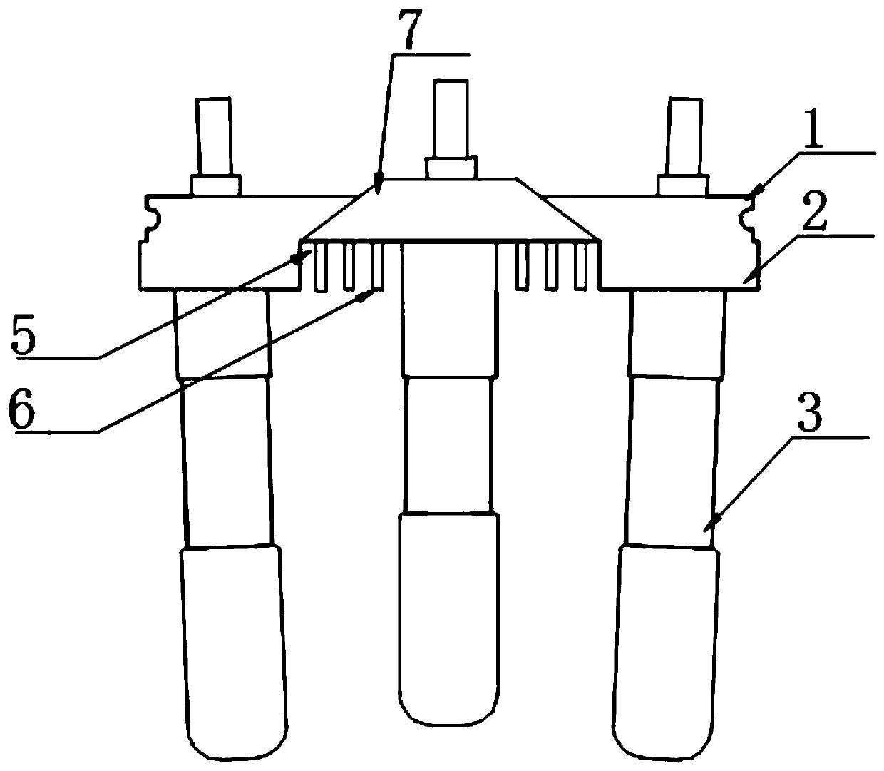
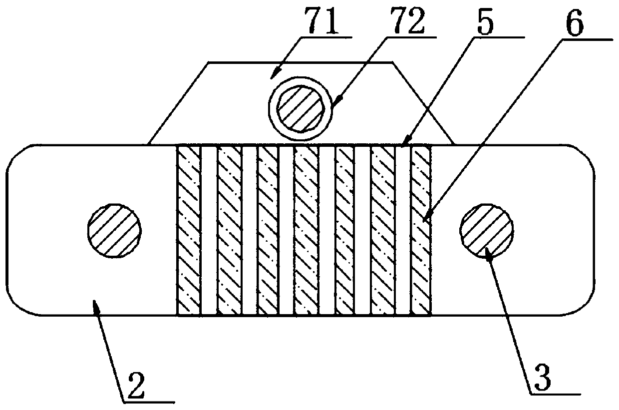
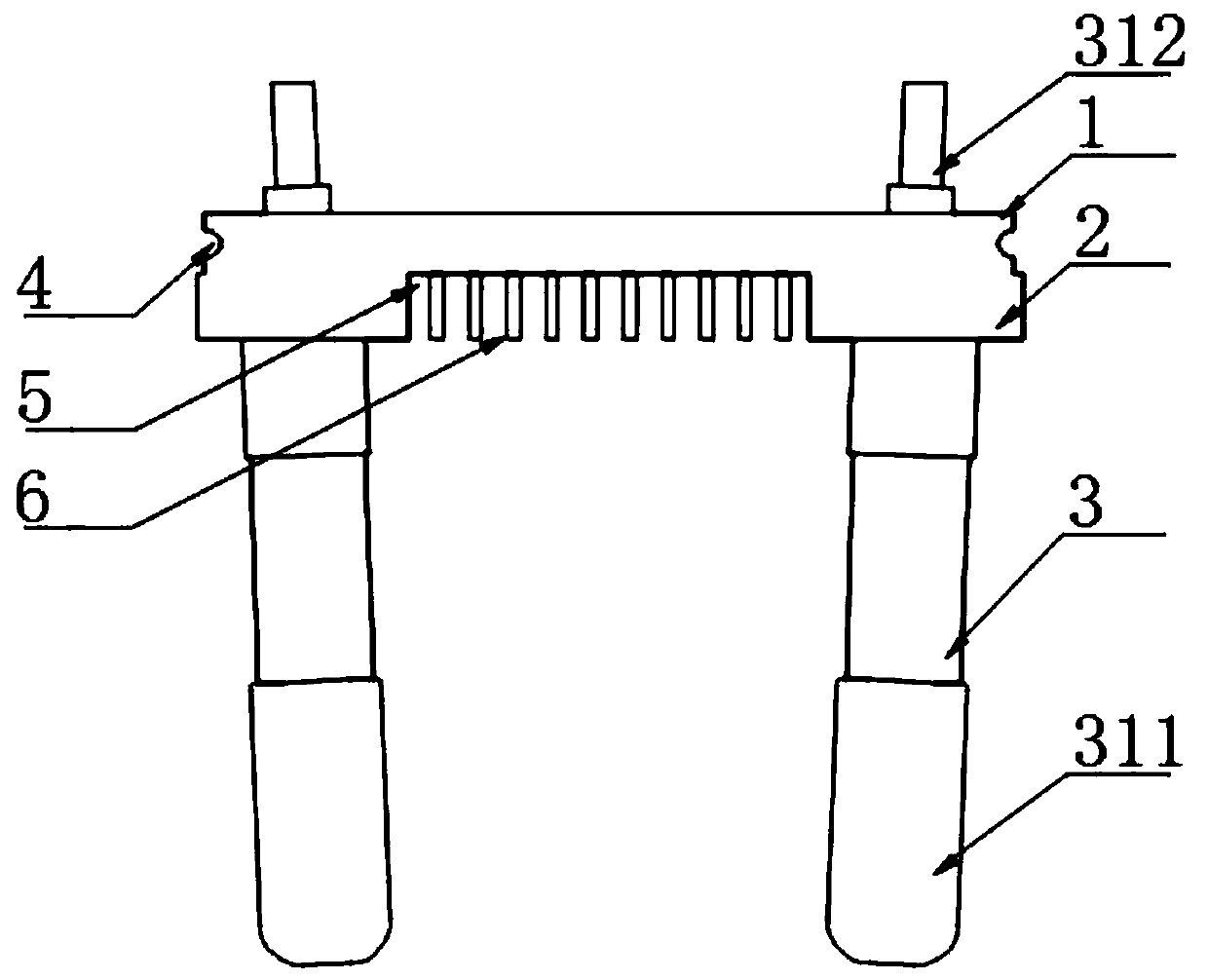
[0034] according to Figure 1-6 A charger pin shown includes a plug body 1, which is characterized in that: the plug body 1 is composed of a substrate 2 and a pin assembly 3, two of the pin assemblies 3 are symmetrically distributed at both ends of the substrate 2, and the pin The component 3 is composed of a conductive hardware cylinder 31 and a sealing surface 32, the sealing surface 32 is set outside the middle of the conductive hardware cylinder 31, positi...


PUM


Abstract

The invention discloses a charger pin and a production technology thereof, and relates to the field of electric appliance assembly manufacture. The charger pin comprises a pin body which is composed of a substrate and pin assemblies, the two pin assemblies are symmetrically distributed at the two ends of the substrate, each pin assembly is composed of a conductive hardware cylinder and a glue sealing surface arranged in the outer side of the middle portion of the conductive hardware cylinder, the two sides of the substrate are provided with positioning slots respectively, and one side of the substrate is provided with a groove. The conductive hardware cylinders are processed to serve as conductive insertion rods, the two conductive insertion rods are symmetrically and inclinedly placed ina casting cavity, the casting cavity is buckled, a rubber solution is injected to implement casting, the rubber solution enters the casting cavity via first and second branch channels, the pin body isprepared after molding, the integrated degree is high, parts are convenient to produce, the casting cavity highly matches the conductive hardware cylinders, the difficulty in placing the conductive cylinders is reduced, the yield rate of injection molding is improved, and the injection molding quality is improved.

Description

technical field [0001] The invention relates to the field of electrical component manufacturing, and more specifically, the invention relates to a charger pin and a production process thereof. Background technique [0002] The charger pin is used for the internal connector of the charging plug, which plays the role of internal conduction and external insulation. Generally, the charger pin is integrally cast by the conductive rod and the insulating rubber. [0003] There are two main types of existing injection molding processes: (1) The diameter of the conductive cylinder is used as the sealing surface, the conductive cylinder is placed in the mold cavity, the cavity is well placed for the conductive cylinder, and the placement and the size of the conductive cylinder The fit tolerance needs to be controlled within ±0.02mm to ensure no glue leakage at the sealing port; (2) Use the spring force to support the conductive cylinder, and use the end face of the conductive cylinder...

Claims


Application Information

Patent Timeline
Patent Type & Authority Applications(China)
IPC IPC(8): H01R13/04H01R13/405H01R13/50H01R13/504H01R13/512H01R13/648H01R43/16H01R43/20H01R43/24H02J7/00
CPCH01R13/405H01R13/04H01R13/50H01R13/504H01R13/512H01R13/648H01R43/16H01R43/20H01R43/24H02J7/0042
Inventor 陈志辉
Owner 广州正业科技有限公司
Why Eureka
Try Eureka