
Train de-icing device and method

A technology for trains and main pipes, applied in the field of train deicing devices, which can solve the problems of deteriorating working conditions of workers, rising working environment temperature, and limited storage time, and achieve the effects of improving deicing efficiency, mild working conditions, and fast heating speed

Inactive Publication Date: 2019-08-09
HARBIN INST OF TECH
View PDF8 Cites 1 Cited by
  • Summary
  • Abstract
  • Description
  • Claims
  • Application Information

AI Technical Summary

Problems solved by technology

Existing deicing solutions are mainly aimed at road surfaces, substation equipment or high-voltage wires, etc., but there are few deicing methods for trains, especially high-speed trains, and the existing deicing technologies for trains have high energy consumption and high deicing requirements , greater impact on the train, lower efficiency, inconvenient operation and control, etc.
[0003] At present, the existing train deicing methods in my country mainly have the following forms: one is to use thermal energy to melt snow and deicing, increase the temperature of the maintenance warehouse, increase heat radiation, increase radiators, infrared heating equipment, etc., and its disadvantages are low efficiency and energy consumption. Large, large investment, large land occupation
The second is mechanical energy deicing, manual deicing with rubber hammers, etc., labor-intensive, low efficiency, ice-covered maintenance cannot be carried out normally, de-icing is not complete, and the storage time is limited, so it is impossible to quickly and efficiently de-icing
These methods not only consume a lot of manpower and material resources, but also have unsatisfactory ice-melting effects and ice-melting rates.
In addition, in actual operation, the hot air deicing system will cause the temperature of the working environment to rise sharply, and sometimes the air temperature in the working space can reach above 50°C, seriously deteriorating the working conditions of workers and reducing work efficiency
If the remaining water on the chassis and bogie is not removed in time after hot air deicing, it will cause re-icing

Method used


Image

  • Train de-icing device and method
  • Train de-icing device and method
  • Train de-icing device and method

Examples


Embodiment Construction

[0035] The technical solutions in the embodiments of the present invention will be clearly and completely described below in conjunction with the drawings in the embodiments of the present invention.

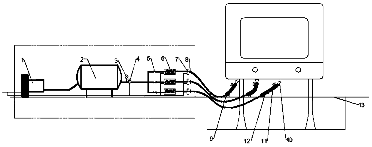
[0036] see figure 1 Describe this embodiment, a train deicing device, characterized in that it includes an air outlet mechanism, a heating mechanism, an air supply mechanism, an air supply main pipe and an air supply branch pipe, the air outlet mechanism is connected with the air supply main pipe, and the air outlet mechanism Provide stabilized pressure gas into the main air supply pipe. Several air supply branch pipes are connected to the air supply main pipe. A heating mechanism is provided on each of the air supply branch pipes. The heating mechanism includes a heater 6 and a temperature controller. 7. The heater 6 and the temperature controller 7 are respectively fixedly connected to the air supply branch pipe, the temperature controller 7 is located at the rear end of the h...


PUM


Abstract

The invention provides a train de-icing device and method, belongs to the technical field of train de-icing, and particularly relates to a train de-icing device and method. The problems that existingde-icing technologies for trains have the disadvantages of large energy consumption, high de-icing requirements, great impact force on the trains, low efficiency, and inconvenient operation and control are solved. The train de-icing device comprises an air outlet mechanism, a heating mechanism, an air supplying mechanism, an air supplying header pipe and an air supplying branch pipe. The train de-icing device and method are mainly used for de-icing the bottom and side frozen trains in cold areas.

Description

technical field [0001] The invention belongs to the technical field of train deicing, in particular to a train deicing device and a deicing method. Background technique [0002] Snow and icing exist in most parts of my country in winter, especially in the Northwest and Northeast of China, when trains run in low temperature environment for a long time, snow and icing are unavoidable. If the snow is not removed in time, it may cause the failure of the train brake system and bearing components. The adhesion of ice and snow may also damage the coupler, the cable of the carriage, cause serious damage to the transportation facilities, and cause huge economic losses to the construction unit. Therefore, it is necessary to melt the ice of train-related equipment. Existing deicing solutions are mainly aimed at road surfaces, substation equipment or high-voltage wires, etc., but there are few deicing methods for trains, especially high-speed trains, and the existing deicing technolog...

Claims


Application Information

Patent Timeline
IPC IPC(8): B60S3/00B60S3/04
CPCB60S3/006B60S3/04
Inventor 张晗冰于沛鑫
Owner HARBIN INST OF TECH
Learn More