A wind power generator main shaft provided with a protective layer and its protective layer attachment process

A technology for wind power generators and protective layers, applied to shafts, shafts and bearings, mechanical equipment, etc., can solve problems such as difficult to control uniformity, complicated painting process, and difficult to spray evenly, achieving remarkable thermal stability and simple processing technology , good anti-corrosion effect

Active Publication Date: 2021-05-25
JIANGYIN ZENKUNG FORGING CO LTD
View PDF16 Cites 0 Cited by
  • Summary
  • Abstract
  • Description
  • Claims
  • Application Information

AI Technical Summary

Problems solved by technology

For the construction of the anti-corrosion coating on the inner hole wall and outer surface of the wind power main shaft, manual spraying is still used, but due to the complicated painting process, it is difficult to spray evenly, and it is time-consuming, labor-intensive, low-efficiency, and serious to environmental pollution; In particular, sandblasting and lighting will seriously pollute the environment.
At present, the solution to the uneven spraying and inconsistent quality of the inner hole and surface of the wind power spindle is: through manual inspection, re-spraying for unqualified parts is really troublesome, and it is still difficult to control the uniformity

Method used


Image

  • A wind power generator main shaft provided with a protective layer and its protective layer attachment process
  • A wind power generator main shaft provided with a protective layer and its protective layer attachment process
  • A wind power generator main shaft provided with a protective layer and its protective layer attachment process

Examples


Embodiment Construction

[0037] The specific implementation manners of the present invention will be further described below in conjunction with the drawings and examples. The following examples are only used to illustrate the technical solution of the present invention more clearly, but not to limit the protection scope of the present invention.

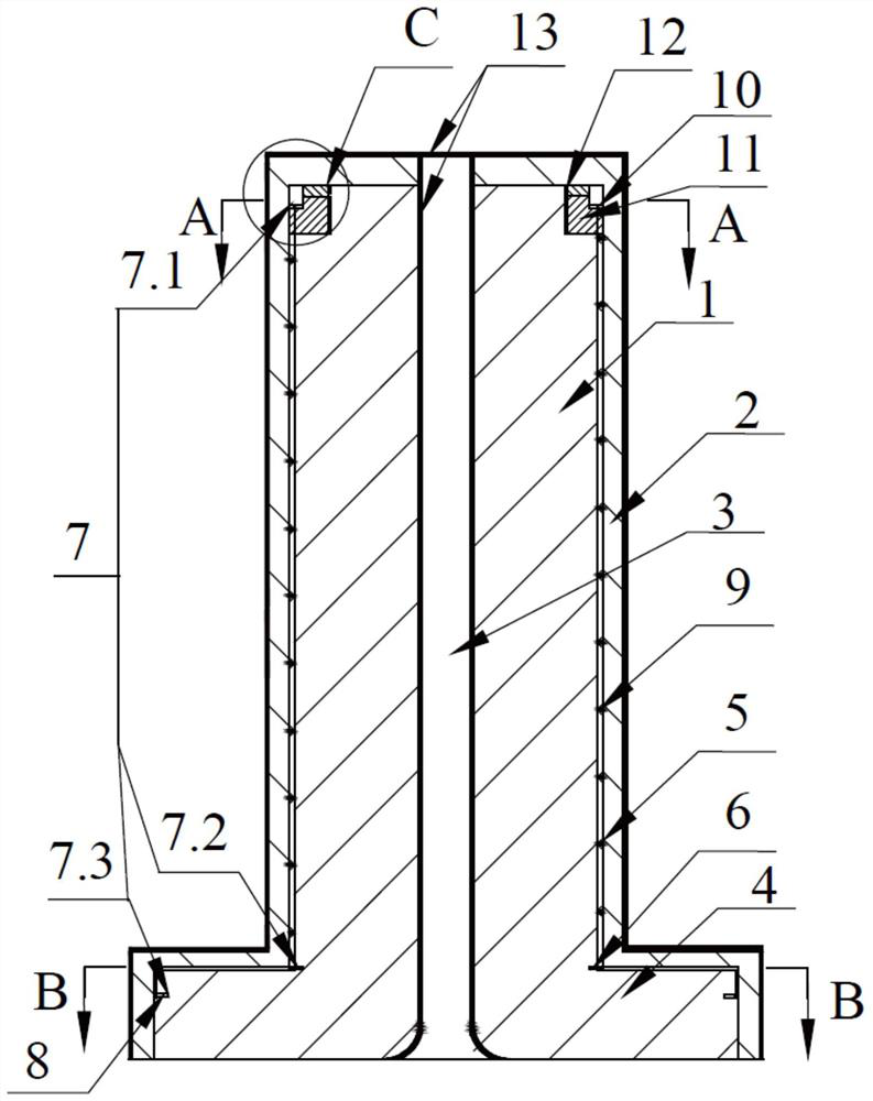
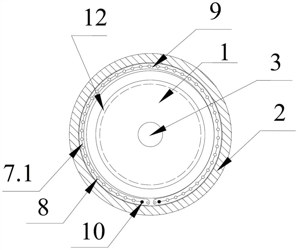
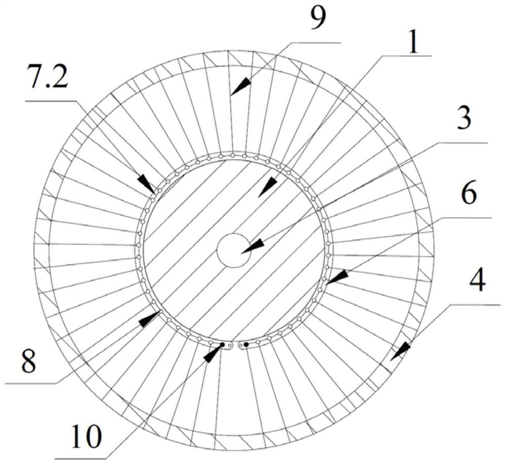
[0038] Such as Figure 1~5 As shown, the present invention is a wind-driven generator main shaft provided with a protective layer, a Teflon surface layer 13 is attached to the surface of the wind-driven generator main shaft, and a reinforcement layer is arranged in the middle of the generator main shaft, and the reinforcement layer is carbon fiber Silk or carbon fiber membrane.

[0039] In order to facilitate the firm combination between Teflon and the surface of the wind power main shaft, and make its attachment process simple and easy to automate, the preferred embodiment of the present invention is that the Teflon surface layer 13 is sprayed on the gene...


PUM

PropertyMeasurementUnit
thicknessaaaaaaaaaa

Abstract

A main shaft of a wind power generator provided with a protective layer, a Teflon surface layer (13) is attached to the surface of the main shaft of the wind power generator, and a reinforcement layer is arranged in the middle of the main shaft of the generator, and the reinforcement layer is carbon fiber wire (9) or carbon fiber membrane. In addition, it also discloses a protective layer attachment process, including removing all the grease on the surface of the workpiece to be coated, using an organic solvent to dissolve the grease and heating it to make it completely volatilize, and using sandblasting to clean the workpiece and make the surface rough. Powder spraying, the Teflon powder particles are blown out of the trap by compressed air, so that the powder particles are attracted by the workpiece and attached to it, and the workpiece is heated to a temperature higher than the melting temperature of the powder material. The powdery particles are coated on it and melted during the spraying process, dried and sintered, and the workpiece is heated in a heating furnace until an irreversible reaction occurs, the coating material melts, and forms a network structure with the bonding agent, and the workpiece Take it out of the oven and let it cool down to room temperature naturally.

Description

technical field [0001] The invention relates to the technical field of wind power generators, in particular to a main shaft of a wind power generator provided with a protective layer and a process for attaching the protective layer. Background technique [0002] With the continuous development of wind power technology, the development of large-capacity units has gradually established its position in the wind power industry. From a technical point of view, large-capacity units can reduce the operation and maintenance costs of wind farms and improve market competitiveness. In the world wind power market, the stand-alone capacity of wind turbines continues to increase. In 2014, the wind turbines with the largest stand-alone capacity in my country reached 10MW. [0003] With the maturity of the technology, the wind turbine technology is developing in the direction of increasing the unit capacity, reducing the weight per kilowatt, and improving the conversion efficiency. Reduci...

Claims


Application Information

Patent Timeline
Patent Type & Authority Patents(China)
IPC IPC(8): F16C3/02B23P15/14
CPCB23P15/14F16C3/02
Inventor 刘圣祥申吉余兰驹戚振华
Owner JIANGYIN ZENKUNG FORGING CO LTD
Why Eureka
Try Eureka