
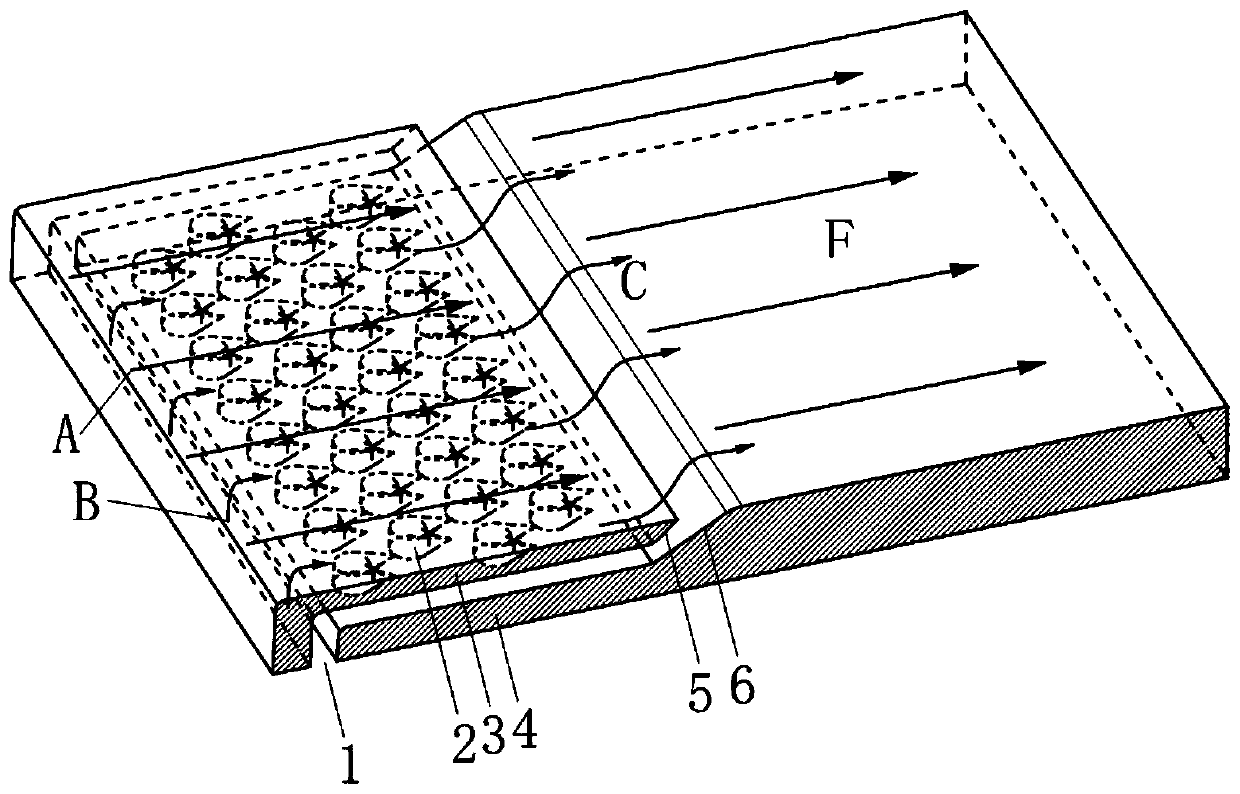
Grid seam cooling structure with fishtail-shaped turbulent flow columns

A cooling structure, fishtail-shaped technology, applied in the direction of the stator, engine components, machines/engines, etc., to reduce flow resistance and enhance wall-adherence

Inactive Publication Date: 2019-08-16
NORTHWESTERN POLYTECHNICAL UNIV
View PDF7 Cites 5 Cited by
  • Summary
  • Abstract
  • Description
  • Claims
  • Application Information

AI Technical Summary

Problems solved by technology

Previously, the two-dimensional slit air film cooling structure was not widely used in blade cooling because of structural strength issues, but the improvement of material technology and processing technology has made the air film slit structure widely used in turbine blades.

Method used


Image

  • Grid seam cooling structure with fishtail-shaped turbulent flow columns
  • Grid seam cooling structure with fishtail-shaped turbulent flow columns
  • Grid seam cooling structure with fishtail-shaped turbulent flow columns

Examples


Embodiment 1

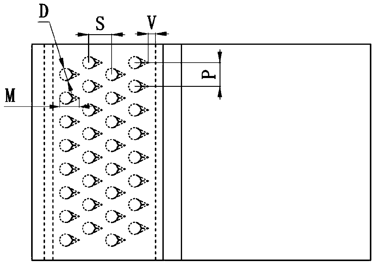
[0029] This embodiment is a grid slot cooling structure with a fishtail-shaped spoiler applied to the turbine guide vane. The air supply cavity 7 and the suction surface grid slot channel 8 are arranged on the suction surface of the turbine blade, provided by the air supply cavity 7. Cold air, the cold air forms an air film at the outlet after passing through the grid slot channel 8 on the suction surface. Among them, four rows of fishtail-shaped spoiler columns are arranged in parallel in the grid slot channel 8 on the suction surface, and the corners of the diversion slope are rounded. In this embodiment, the cylinder diameter D of the fishtail spoiler is 0.8 mm, and the length of the fishtail spoiler along the flow direction is 1.5 mm. The transverse spacing P of the fishtail spoilers is 1.6mm, the flow spacing S of the fishtail spoilers is 1.6mm, and the front and rear rows of fishtail spoilers are arranged in parallel. The width W of the air intake cavity is 1.6mm, the h...

Embodiment 2

[0031] This embodiment is a grid slot cooling structure with a fishtail spoiler column applied to the turbine guide vane. The air supply cavity 9 and the pressure surface grid slot channel 10 are arranged on the pressure surface of the turbine blade, provided by the air supply cavity 9. Cold air, the cold air forms an air film at the outlet after passing through the grid slit channel 10 on the pressure surface. Among them, three rows of fishtail-shaped spoiler columns are arranged in the grid slot channel, and the corners of the outlet diversion slope are rounded. The diameter D of the fishtail spoiler is 1.2 mm, and the length of the fishtail spoiler along the flow direction is 1.8 mm. The transverse pitch P of the fishtail spoiler is 2.0mm, the space between the flow directions S of the fishtail spoiler is 2.0mm, and the fishtail spoilers in the front and rear rows are arranged in fork rows. The width W of the air intake cavity is 2.0mm, the height H of the cold air channel...


PUM


Abstract

The invention discloses a grid seam cooling structure with fishtail-shaped turbulent flow columns, and relates to a gas turbine cooling technology. The structure is used for cooling turbine blades ofa gas turbine. The cooling structure is formed by arranging the fishtail-shaped turbulent flow columns in a two-dimensional grid seam and arranging a double-inclined-surface outlet at an outlet, and comprises an air inlet cavity, a lip plate, a bottom plate, the fishtail-shaped turbulent flow columns, a lip plate flow guide inclined surface and a bottom plate flow guide inclined surface. Fishtail-shaped structures at the rear ends of the fishtail-shaped turbulent flow columns are designed according to bionics, flow separation and backflow vortex behind a conventional cylindrical turbulent flowcolumn can be greatly weakened, and then flowing resistance in a grid seam channel is reduced; the lip plate flow guide inclined surface can eliminate the backflow vortex phenomenon at the outlet ofthe grid seam structure, and the flow resistance at the outlet is reduced; and a double-inclined-surface air outlet channel formed by the lip plate and the bottom plate reduces the normal momentum ofair flow, rounding at corners of the flow guide inclined surfaces enhances adherence of cold air, and after flowing through the grid seam structure, the cold air forms covering on the downstream side,and plays a role in protection of the blades.

Description

technical field [0001] The invention relates to the technical field of cooling of turbine blades of a gas turbine, in particular to a grid slot cooling structure with a fishtail-shaped spoiler column. [0002] technical background [0003] As a complex and delicate mechanical device, gas turbine is widely used in the field of industrial production. It is often used as the power output equipment of aircraft and ships, and is an indispensable part of the current industrial system. According to the principle of thermodynamics, increasing the turbine inlet temperature of a gas turbine can effectively increase its working power and efficiency, but this is limited by the heat resistance limit of the turbine blade material. In order to take into account the safety of the blade and the efficiency of the gas turbine, the turbine blade must be cooled. . As an external cooling method, film cooling is widely used in the cooling structure design of high-temperature components of gas turb...

Claims


Application Information

Patent Timeline
IPC IPC(8): F01D9/02F01D25/12
CPCF01D9/02F01D25/12F05D2260/202
Inventor 朱惠人姚春意张博伦刘存良张正
Owner NORTHWESTERN POLYTECHNICAL UNIV
Learn More