Check patentability & draft patents in minutes with Patsnap Eureka AI!

Voltage-multiplying RF rectifying antenna

A technology of rectifier antenna and voltage doubler rectifier circuit, applied in the direction of antenna, antenna grounding switch structure connection, radiating element structure form and other directions, can solve the problems of large size of radio frequency rectifier, high output voltage, difficult to obtain, etc., and achieve cost Low cost, high integration and simple structure

Active Publication Date: 2019-08-16
NINGBO UNIV
View PDF12 Cites 2 Cited by
  • Summary
  • Abstract
  • Description
  • Claims
  • Application Information

AI Technical Summary

Problems solved by technology

Traditional RF rectennas usually use an unbalanced single-port feed mode, and the input impedance is generally designed as a pure resistance form such as 50Ω or 75Ω. Therefore, the RF rectenna needs to be equipped with an additional impedance matching circuit to realize the input impedance of the antenna and the rectification circuit. Conjugate matching of impedance, which will result in a larger size of the RF rectenna
In addition, the input power received by the rectenna usually changes in a wide range, and it is difficult for the traditional RF rectenna to achieve low input power and high input power while achieving high conversion efficiency
In particular, even if some designs can achieve better conversion efficiency in the low input power range, it is difficult to obtain a higher output voltage, and thus cannot drive the load circuit

Method used


Image

  • Voltage-multiplying RF rectifying antenna
  • Voltage-multiplying RF rectifying antenna
  • Voltage-multiplying RF rectifying antenna

Examples


Embodiment 1

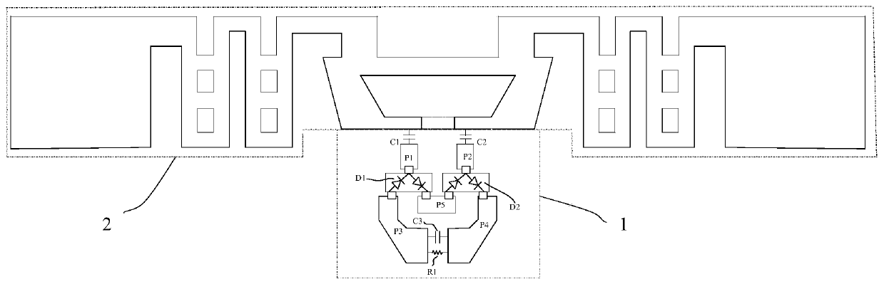
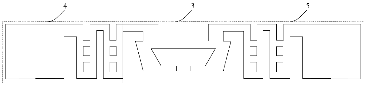
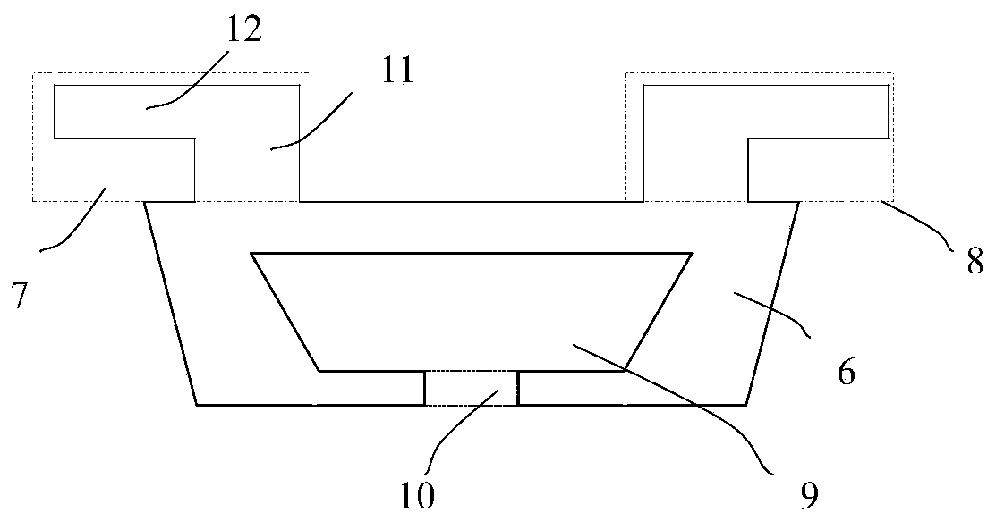
[0019] Embodiment 1: A voltage-doubling radio-frequency rectifying antenna, including an antenna and a voltage-doubling rectifier circuit 1, the antenna is realized by a T-matching structure symmetrical vibrator antenna 2 arranged in a copper-clad manner on the upper surface of a PCB dielectric plate, and the voltage-doubling rectifier circuit 1 adopts a differential charge pump circuit structure, the voltage doubler rectifier circuit 1 is formed by direct welding of lumped components, and the voltage doubler rectifier circuit 1 is connected to the antenna by welding.

[0020] In this example, if Figure 1~5As shown, the voltage doubler rectifier circuit 1 includes a first capacitor C1, a second capacitor C2, a third capacitor C3, a first rectifier diode D1, a second rectifier diode D2, a first resistor R1, a first PIN pin P1, a second PIN The pin P2, the third PIN pin P3, the fourth PIN pin P4 and the fifth PIN pin P5, the first rectifier diode D1 and the second rectifier dio...


PUM


Abstract

The invention discloses a voltage-multiplying RF rectifying antenna, comprising an antenna and a voltage-multiplying rectifying circuit, and characterized in that the antenna is realized by a T-matching structure symmetric vibrator antenna which is arranged on the upper surface of a PCB dielectric board in a copper-clad manner; and the voltage-multiplying rectifying circuit uses a differential charge pump circuit structure, is formed by directly soldering lumped elements, and is soldered to the antenna. The voltage-multiplying RF rectifying antenna is small in size, and has high rectificationefficiency and high output voltage within a current wide input power range.

Description

technical field [0001] The invention relates to a radio frequency rectifying antenna, in particular to a voltage doubler type radio frequency rectifying antenna. Background technique [0002] Microwave wireless power transmission and energy harvesting technologies are mainly used for long-distance energy transmission and energy harvesting. With the gradual maturity of high-power microwave sources and the improvement of the performance of microwave rectifier diodes, the rectification efficiency of wireless energy transmission systems is also improving. In recent years, with the development of the Internet of Things technology, the concept of the Internet of Everything has gradually become popular, but the power supply problem of the Internet of Things nodes has become one of its bottleneck technologies, and the microwave wireless power transmission and energy harvesting technology will provide the power supply problem for this type of scene. An effective technical means. As ...

Claims


Application Information

Patent Timeline
Patent Type & Authority Applications(China)
IPC IPC(8): H01Q1/38H01Q1/50H01Q23/00
CPCH01Q1/38H01Q1/50H01Q23/00
Inventor 王健张辉涂世琼
Owner NINGBO UNIV
Features
  • R&D
  • Intellectual Property
  • Life Sciences
  • Materials
  • Tech Scout
  • Unparalleled Data Quality
  • Higher Quality Content
  • 60% Fewer Hallucinations
Learn More