
Portable non-mydriasis fundus camera

A mydriasis-free, portable technology, used in ophthalmoscopes, eye testing equipment, medical science, etc., can solve the problems of human eye damage, poor imaging quality, low filming rate, etc. The quality of the film, the effect of safe and convenient use

Pending Publication Date: 2019-08-20
南京览视医疗科技有限公司
View PDF6 Cites 1 Cited by
  • Summary
  • Abstract
  • Description
  • Claims
  • Application Information

AI Technical Summary

Problems solved by technology

Portable and handheld fundus cameras appearing in the domestic and foreign markets, although the optical system is simple in structure, but lack of working distance positioning and precise focusing optical path, the operator is easy to shake when using it, it is difficult to find the pupil, and the working distance and precise focusing cannot be guaranteed , leading to problems such as poor imaging quality and low film formation rate; and the infrared light of the existing portable fundus camera is usually projected to the fundus during the observation process, which will cause certain damage to the human eye

Method used


Image

  • Portable non-mydriasis fundus camera
  • Portable non-mydriasis fundus camera
  • Portable non-mydriasis fundus camera

Examples


Embodiment 1

[0027] This embodiment provides a portable non-mydriatic fundus camera, the fundus camera includes an optical system and a control unit; wherein the optical system includes a positioning optical path, a focusing optical path, and an illumination imaging optical path; the positioning optical path, the The focusing optical path and the illumination imaging optical path share a set of zoom objective lenses and an image sensor; the positioning optical path and the focusing optical path both include at least one double optical wedge;

[0028] The control unit is used to control the positioning optical path, the focusing optical path and the illumination imaging optical path, and at the same time process the captured fundus images.

[0029] Specifically, the zoom objective lens includes an eyepiece objective lens and a zoom lens.

[0030] Preferably, the focusing optical path and the illumination imaging optical path share some optical components.

[0031] Specifically, the shared ...

Embodiment 2

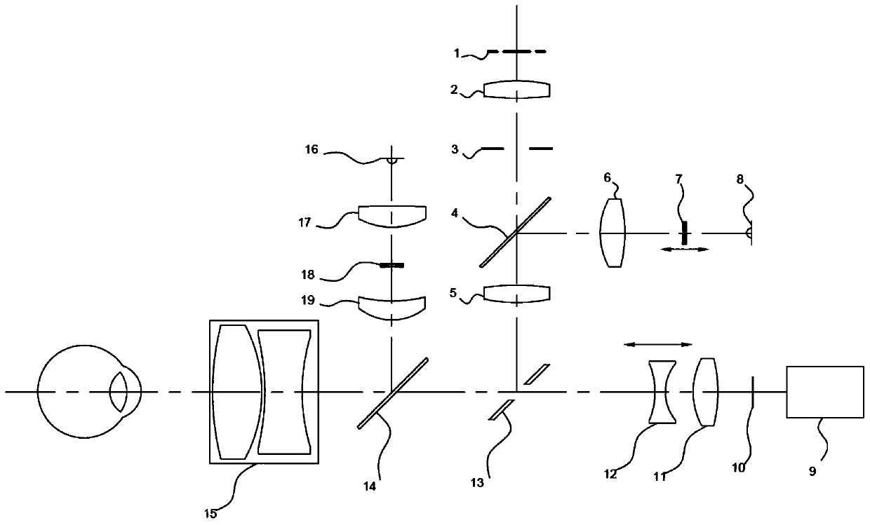
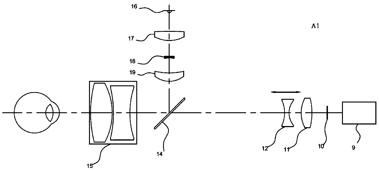
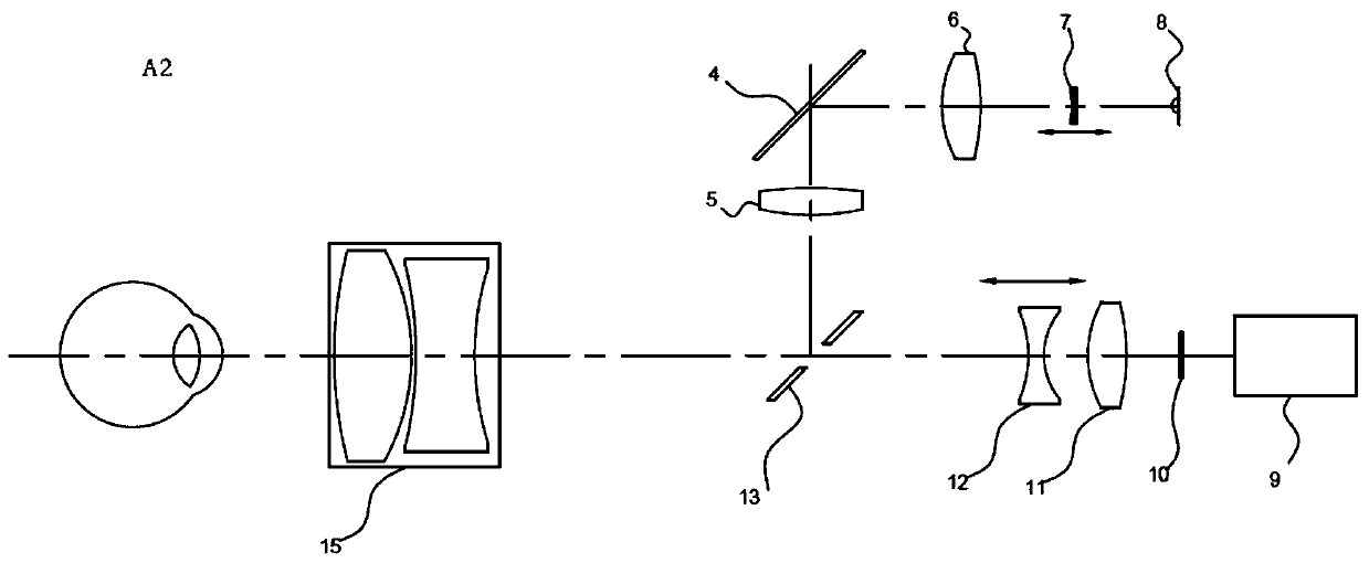
[0045] Such as figure 1 As shown, it is a schematic structural diagram of a portable non-mydriatic fundus camera disclosed in this embodiment; it includes an optical system A and a control unit 9, wherein the optical system A includes a positioning optical path A1, a focusing optical path A2, and an illumination imaging optical path A3 ; The positioning optical path A1 includes a working distance lens group, and the focusing optical path A2 includes a focusing lens group;

[0046] Specifically, the optical system A includes: a white LED ring light panel 1, a first condenser lens 2, an aperture stop 3, a half mirror 4, a second condenser lens 5, a third condenser lens 6, a first double wedge 7, and an infrared LED lamp 8 , image sensor 10, adapter mirror 11, zoom mirror 12, ring mirror 13, half mirror 14, eyepiece objective lens 15, white light LED lamp 16, the fourth condenser 17, the second double wedge 18, the fifth condenser 19.

[0047] Further, the optical system A adopt...


PUM


Abstract

The invention discloses a portable non-mydriasis fundus camera, and relates to the field of medical ophthalmic optics instruments. The portable non-mydriasis fundus camera comprises an optical systemand a control unit, wherein the optical system comprises a positioning light path, a focusing light path and an illumination imaging light path; a group of vari-focus lens and an image sensor are shared by the positioning light path, the focusing light path and the illumination imaging light path; the positioning light path and the focusing light path respectively comprise one or more dual-opticalwedges; and the control unit is used for controlling the positioning light path, the focusing light path and the illumination imaging light path, and is used for performing treatment on the shot fundus images. The portable non-mydriasis fundus camera disclosed by the invention is small in volume, and convenient to carry, can also realize quick positioning of working distance and accurate focusing, and the photo forming quality and photo forming rate are simultaneously guaranteed; and a user can safely and conveniently use the portable non-mydriasis fundus camera.

Description

technical field [0001] The invention relates to the field of medical ophthalmic optical instruments, in particular to a portable non-mydriatic fundus camera. Background technique [0002] As a medical ophthalmology examination equipment, the fundus camera is used to observe and acquire fundus images of the human eye, such as observing whether the retina, optic disc, and blood vessel distribution of the fundus are abnormal. The blood vessels in the fundus are the only capillaries in the human body that can be directly observed through the body surface. Using the fundus camera, doctors can use it for early diagnosis of fundus diseases, kidney diseases, high blood pressure, diabetes and other diseases. [0003] At present, the desktop fundus cameras on the market generally have the disadvantages of complex optical system structure, large size and non-portability, need to configure special software and external computer, and also need external power supply, and high cost; and po...

Claims


Application Information

Patent Timeline
IPC IPC(8): A61B3/12A61B3/15
CPCA61B3/0008A61B3/0016A61B3/1208A61B3/152A61B3/158
Inventor 沈小厚
Owner 南京览视医疗科技有限公司
Learn More