Non-uniform transverse longitudinal groove turbine outer ring structure

A non-uniform, horizontal and vertical technology, applied in the direction of the stator, engine components, machine/engine, etc., can solve the problems of interfering with the normal and stable flow of the main flow of the blade cascade, the gas flow speed is fast, and the efficiency of the film cooling efficiency is reduced, so as to achieve the improvement Effects of film cooling efficiency, improved gas utilization efficiency, and improved cooling performance

Active Publication Date: 2019-08-20
SHENYANG AEROSPACE UNIVERSITY
View PDF7 Cites 0 Cited by
  • Summary
  • Abstract
  • Description
  • Claims
  • Application Information

AI Technical Summary

Problems solved by technology

After air film cooling is adopted, the leakage fluid in the tip clearance is mixed with the mainstream fluid in the channel, and the flow is very complicated. On the one hand, seepage will form in the leading edge area, resulting in energy loss of the mainstream fluid. On the other hand, the blade pressure surface and suction surface The pressure difference will form a gap leakage flow, thereby dist

Method used


Image

  • Non-uniform transverse longitudinal groove turbine outer ring structure
  • Non-uniform transverse longitudinal groove turbine outer ring structure
  • Non-uniform transverse longitudinal groove turbine outer ring structure

Examples


Embodiment 1

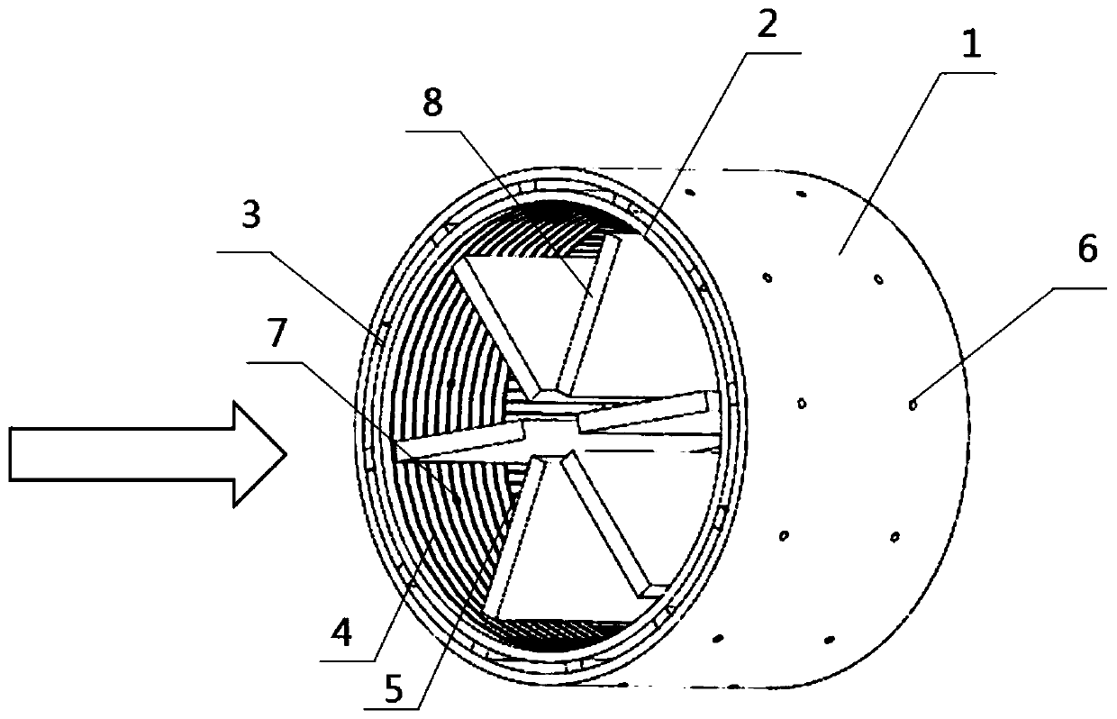
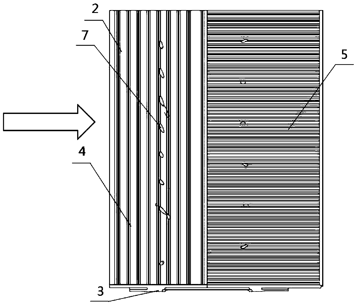
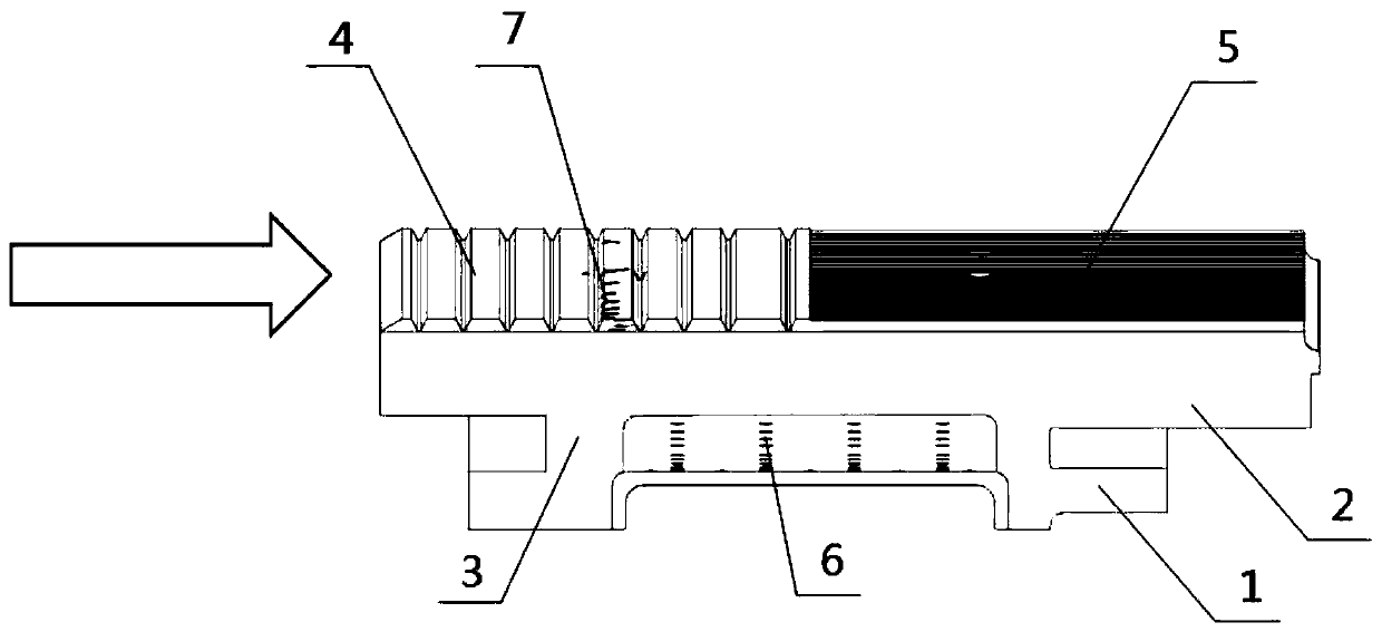
[0023] The axial chord length of the blade 8 is 40mm; the axial length of the outer casing 1 is 50mm, the thickness of the inner casing 2 and the outer casing 1 is 10mm, and the height of the connecting body 3 is 8mm; the inner diameter of the impact hole 6 is 0.8mm, two rows of impact holes 6, each row 30, evenly arranged, the impact angle of the impact hole 6 is 85°; the number of 3 connectors is 12, evenly arranged; two exhaust film holes 7, each exhaust film hole 7 is 30, and the air film hole is 7 The diameter is 0.5mm; the height of the circumferential rib groove 4 is 0.5mm, the gap between the rib grooves is 0.2mm, the width of the rib groove sealing tooth is 1.3mm, the chamfer of the top of the sealing tooth is 62.5°, and the overall length of the circumferential rib groove 4 is 25mm, evenly distributed on the inlet side of the cascade; the height of the axial rib groove 5 is 0.5mm, the width of the bottom of the rib groove is 0.2mm, the width of the rib groove sealing ...

Embodiment 2

[0026] The axial chord length of the blade 8 is 40 mm; the axial length of the outer shell 1 is 50 mm, the thickness of the inner shell 2 and the outer shell 1 is 10 mm, and the height of the connecting body 3 is 8 mm; the diameter of the impact hole 6 is 0.8 mm, and two rows of impact holes 6, each 25 rows, evenly arranged, the impact angle of the impact hole 6 is 90°; the number of 3 connectors is 20, evenly arranged; two exhaust film holes 7, each exhaust film hole 7 is 25, the air film The inner diameter of hole 7 is 0.5mm; the height of circumferential rib groove 4 is 0.5mm, the gap between rib grooves is 0.2mm, the width of rib groove sealing teeth is 0.6mm, the chamfer of the tooth top of sealing teeth is 62.5°, and the circumferential rib groove 4 The overall length is 20mm, evenly distributed on the inlet side of the cascade; the height of the axial rib groove 5 is 0.5mm, the width of the bottom of the rib groove is 0.2mm, the width of the rib groove sealing teeth is 0...

Embodiment 3

[0029]The axial chord length of the blade 8 is 40 mm; the axial length of the outer shell 1 is 50 mm, the thickness of the inner shell 2 and the outer shell 1 is 10 mm, and the height of the connecting body 3 is 8 mm; the inner diameter of the impact hole 6 is 0.8 mm, and two rows of impact holes 6, each There are 25 rows, evenly arranged, and the impact angle of the impact hole 6 is 80°; the number of 3 connectors is 20, evenly arranged; two exhaust membrane holes 7, each exhaust membrane hole 7 is 30, and the air membrane The inner diameter of the hole 7 is 0.5mm; the height of the circumferential rib groove 4 is 0.5mm, the rib groove gap is 0.2mm, and the width of the rib groove sealing teeth is different. mm, increasing successively toward the outlet of the cascade. The top chamfer of the sealing tooth is 62.5°, the overall length of the circumferential rib groove 4 is 30mm, and is unevenly distributed on the inlet side of the cascade; the height of the axial rib groove 5 ...


PUM

PropertyMeasurementUnit
Angle of incidenceaaaaaaaaaa
The inside diameter ofaaaaaaaaaa

Abstract

The invention discloses a non-uniform transverse longitudinal groove turbine outer ring structure. The structure comprises an impact body, wherein the impact body is composed of an inner shell body, an outer shell body and a connecting body, a plurality of impact holes are formed in the outer shell body, rib grooves are formed in the inner wall of the inner shell body, the rib grooves comprise circumferential rib grooves and axial rib grooves, the circumferential rib grooves are formed in the inner wall of the inner shell body along the circumferential direction at an inlet of a blade grid, the plurality of circumferential rib grooves are not uniformly or uniformly distributed on the inner wall of the inner shell body, the axial rib grooves are formed in the inner wall of the inner shell body in the axial direction at an outlet of the blade grid, the plurality of axial rib grooves are uniformly distributed on the inner wall of the inner shell body, a plurality of air film holes are formed in the inner shell body, and the outer shell body and the inner shell body are fixedly arranged through the connecting body. When the fuel gas passes through the rib grooves, due to the obstruction effect of the rib grooves on the fuel gas, the gas speed in the grooves is obviously reduced, compared with a turbine outer ring without a rib groove structure, after the transverse longitudinal groove structure is added, the gap leakage flow is reduced by 1%-3%.

Description

technical field [0001] The invention relates to a gas turbine turbine outer ring structure, in particular to a gas turbine outer ring structure with non-uniform horizontal and vertical grooves. Background technique [0002] The gas turbine rotates the rotor blades through the impact of gas on the rotor blades to output work, and the outer ring structure of the turbine separates the rotating rotor blades from the stationary parts. In the cascade passage, the gas temperature is already higher than the temperature resistance limit of the turbine components, which must be effectively cooled. The outer ring is usually cooled by film cooling, which separates the high-temperature gas in the cascade channel from the outer wall. After air film cooling is adopted, the leakage fluid in the tip clearance is mixed with the mainstream fluid in the channel, and the flow is very complicated. On the one hand, seepage will form in the leading edge area, resulting in energy loss of the mainst...

Claims


Application Information

Patent Timeline
IPC IPC(8): F01D9/00F01D25/12
CPCF01D9/00F01D25/12F05D2260/202
Inventor 张魏张子阳李广超杨鹏寇志海毛晓东
Owner SHENYANG AEROSPACE UNIVERSITY
Why Eureka
Try Eureka