Two-stage hydrogen fuel cell stack gas supply device driven by motor

A technology of fuel cell stack and gas supply device, which is applied to fuel cells, fuel cell additives, electrical components, etc., can solve the problems of poor cooling effect and high cooling energy consumption, and achieves increased stability, increased reaction rate, and improved negative The effect of pressure capacity and use time

Pending Publication Date: 2019-08-20
XECA TURBO TECH (BEIJING) CO LTD
View PDF0 Cites 2 Cited by
  • Summary
  • Abstract
  • Description
  • Claims
  • Application Information

AI Technical Summary

Problems solved by technology

In this way, not only the cooling effect is poor, but also the cooling energy consumption is high

Method used


Image

  • Two-stage hydrogen fuel cell stack gas supply device driven by motor
  • Two-stage hydrogen fuel cell stack gas supply device driven by motor
  • Two-stage hydrogen fuel cell stack gas supply device driven by motor

Examples


Embodiment 1

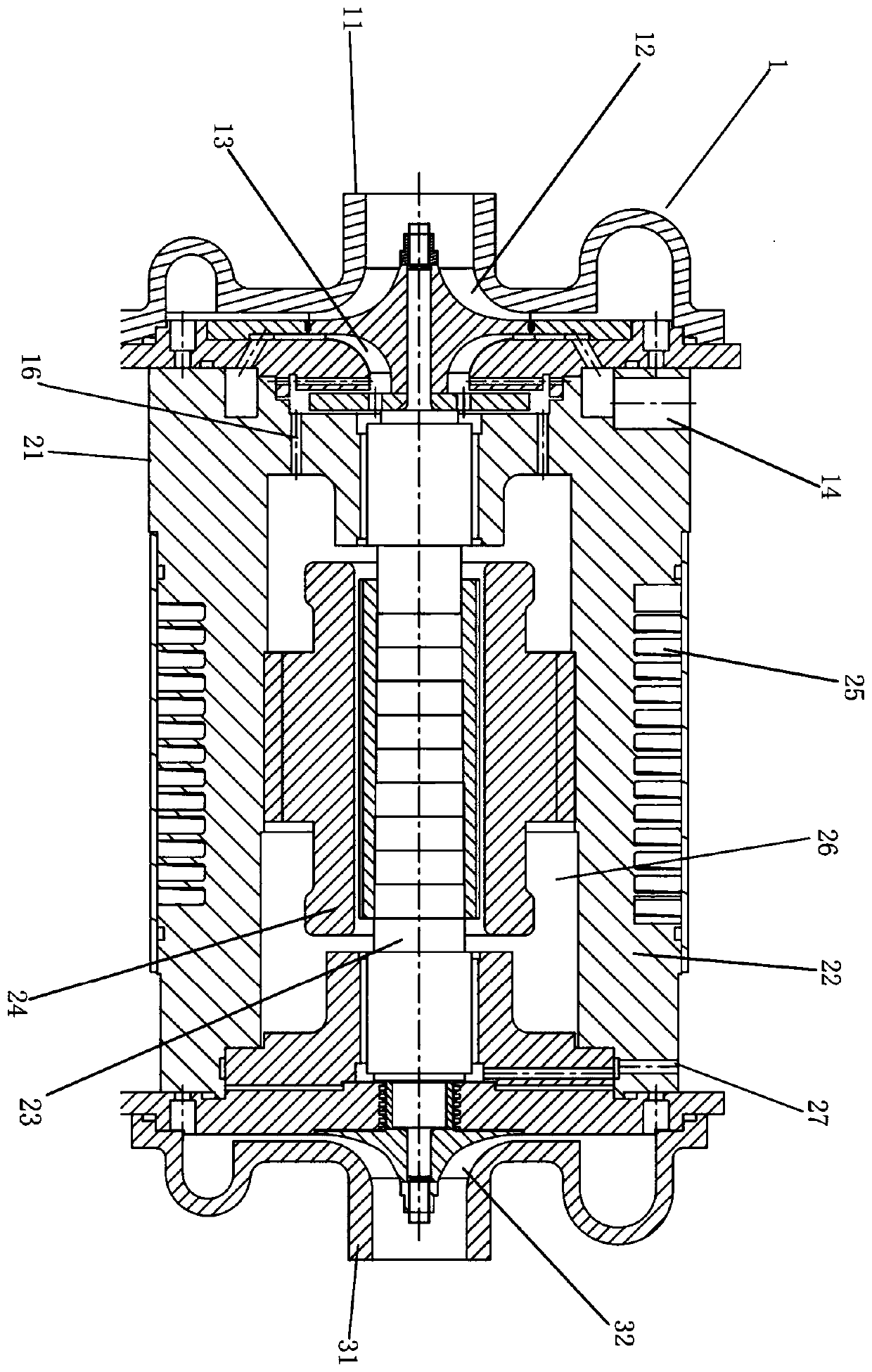
[0025] Such as figure 1 , image 3 as shown in

[0026] A two-stage hydrogen fuel cell stack gas supply device driven by an electric motor, comprising

[0027] Drive motor 2, primary compressor 1, secondary compressor 3 and inter-stage communication pipeline, the drive motor 2 includes a motor housing 21, a motor stator 22, a motor main shaft 23 and a high-speed motor rotor 24, the motor The stator is fixed in the motor housing, the two ends of the motor main shaft are respectively provided with bearings 4, the outer ring of the bearings is connected with the motor housing, and the driving motor is provided with a motor cooling cavity 26 and a cooling exhaust pipe 27 ;

[0028] The first-stage compressor includes a first-stage compressor exhaust volute 11, a first-stage compressor impeller 12, and a first-stage turbine 13. The first-stage compressor impeller and the first-stage turbine rotate coaxially with the motor main shaft. The primary compressor is provided with a pr...

Embodiment 2

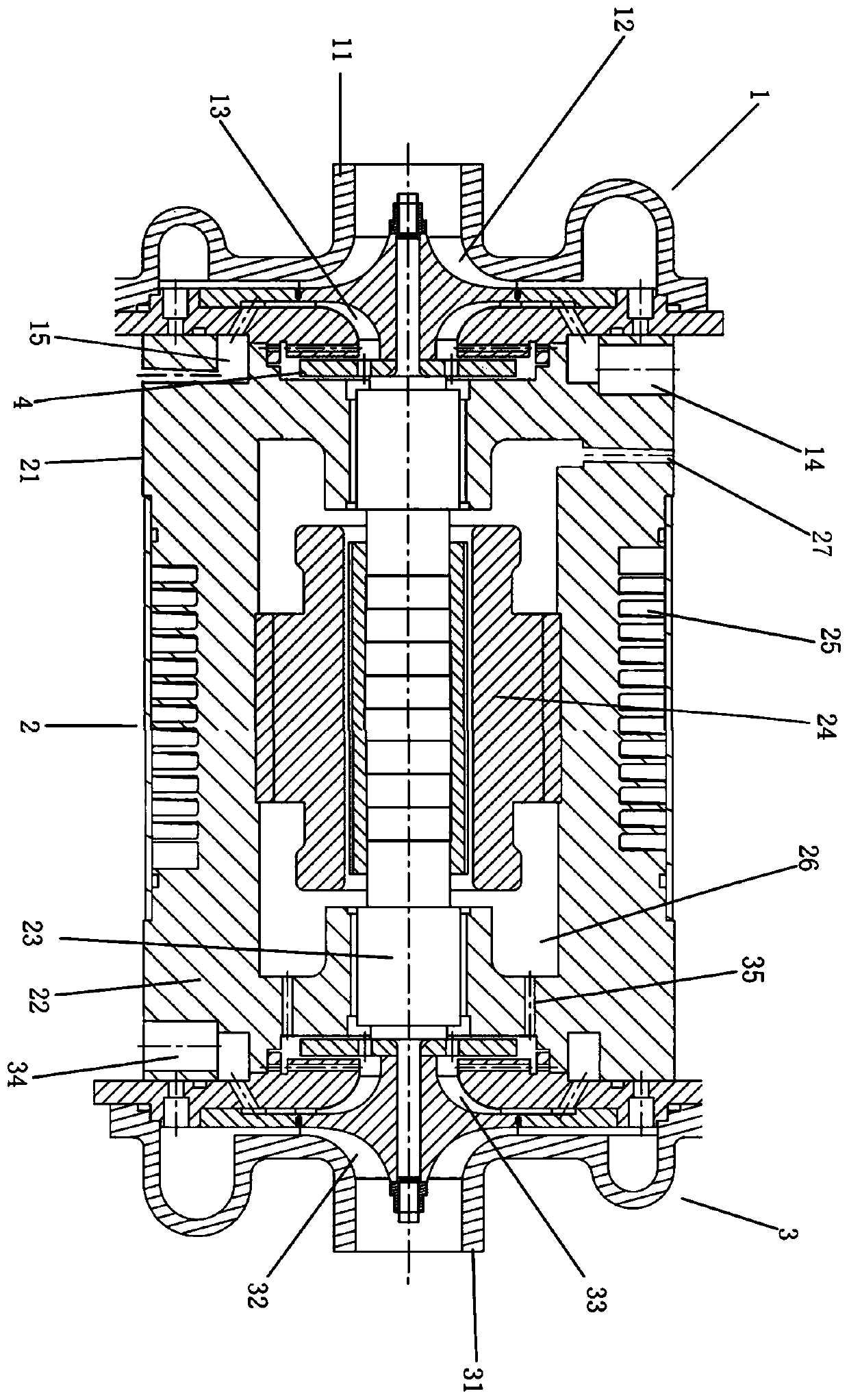
[0031] Such as figure 2 , Figure 4 as shown in

[0032] A two-stage hydrogen fuel cell stack gas supply device driven by a motor, including a drive motor 2, a first-stage compressor 1, a second-stage compressor 3 and an inter-stage communication pipeline, and the drive motor 2 includes a motor housing 21 , the motor stator 22, the motor main shaft 23 and the high-speed motor rotor 24, the motor stator is fixed in the motor housing, the two ends of the motor main shaft are respectively provided with bearings 4, and the outer ring of the bearing is connected with the motor housing, The drive motor is provided with a motor cooling cavity 26 and a cooling exhaust pipe 27; the first-stage compressor includes a first-stage compressor exhaust volute 11, a first-stage compressor impeller 12, and a first-stage turbine 13. The first-stage compressor impeller and the first-stage turbine rotate coaxially with the main shaft of the motor. The first-stage compressor is provided with a fir...


PUM


Abstract

The invention discloses a two-stage hydrogen fuel cell stack gas supply device driven by a motor. The two-stage hydrogen fuel cell stack gas supply device comprises a drive motor, a primary compressor, a secondary compressor and an interstage communicating pipeline. The drive motor comprises a motor shell, a motor stator, a motor main shaft and a high-speed motor rotor; gas is exhausted by a hydrogen fuel cell and enters a turbine, the turbine drives a coaxially rotating gas compressor to reduce the power consumption of the gas compressor and reduce the gas temperature the gas exhausted by thehydrogen fuel cell through the heat release of the turbine, and the gas exhausted by the hydrogen fuel cell enters the drive motor to perform heat exchange for a high-speed motor rotor to reduce thetemperature of the high-speed motor rotor, increase the stability of the motor and improve the negative pressure capacity and the service time of the motor. The two-stage hydrogen fuel cell stack gassupply device cools the system by employing the energy of the tail gas of the fuel cell to improve the power generation efficiency of the fuel cell while reducing the cooling energy consumption.

Description

technical field [0001] The invention relates to the field of hydrogen fuel cell gas supply, in particular to a two-stage hydrogen fuel cell stack gas supply device driven by a motor. Background technique [0002] A fuel cell is an efficient and clean energy conversion device. The air compressor compresses the air and sends it to the cathode side of the fuel cell to provide an oxidant. In the fuel cell, the air reacts electrochemically with hydrogen, and the resulting water is discharged together with the remaining air. The exhaust gas has a higher pressure and can be further utilized. [0003] During high-speed rotation, the motor and bearing will generate a lot of heat. If the heat dissipation is not timely, the temperature will rise sharply and affect its normal operation. The heating of the stator coil of the motor can usually be solved by water cooling, while the heat of the rotor and bearing can only be cooled by the high-pressure exhaust of the compressor. In this w...

Claims


Application Information

Patent Timeline
IPC IPC(8): H01M8/04082H01M8/04111H01M8/04701
CPCH01M8/04201H01M8/04111H01M8/04738Y02E60/50
Inventor 张学锋
Owner XECA TURBO TECH (BEIJING) CO LTD
Why Eureka
Try Eureka