Fuel oil recovery process

A fuel oil and recovery system technology, applied in the preparation of organic compounds, hydrocarbons, organic chemistry, etc., can solve the problems of inability to recover alkanols and ketones, waste resources, and discharge to waste water tanks, etc., and reduce the discharge of hazardous waste. Effect

Active Publication Date: 2019-08-23
LIAOCHENG MEISI NEW MATERIAL TECH CO LTD
View PDF2 Cites 2 Cited by
  • Summary
  • Abstract
  • Description
  • Claims
  • Application Information

AI Technical Summary

Problems solved by technology

Defects of this kind of process recovery: 1. The recovery of fuel oil is intermittent. As the purification tower in the system, the solvent recovery tower for recovering fuel oil mainly has two functions. Before and after the recovery of fuel oil, the equipment must be cleaned by steam. Cooking, the waste water produced is discharged to the waste water tank, which is a waste of resources. 2. Only the light components in the fuel oil can be recovered, and the alcohol and ketone in the heavy components in the tower kettle cannot be recovered, and they are discharged as fuel oil for takeaway

Method used


Image

  • Fuel oil recovery process
  • Fuel oil recovery process

Examples


Embodiment 1

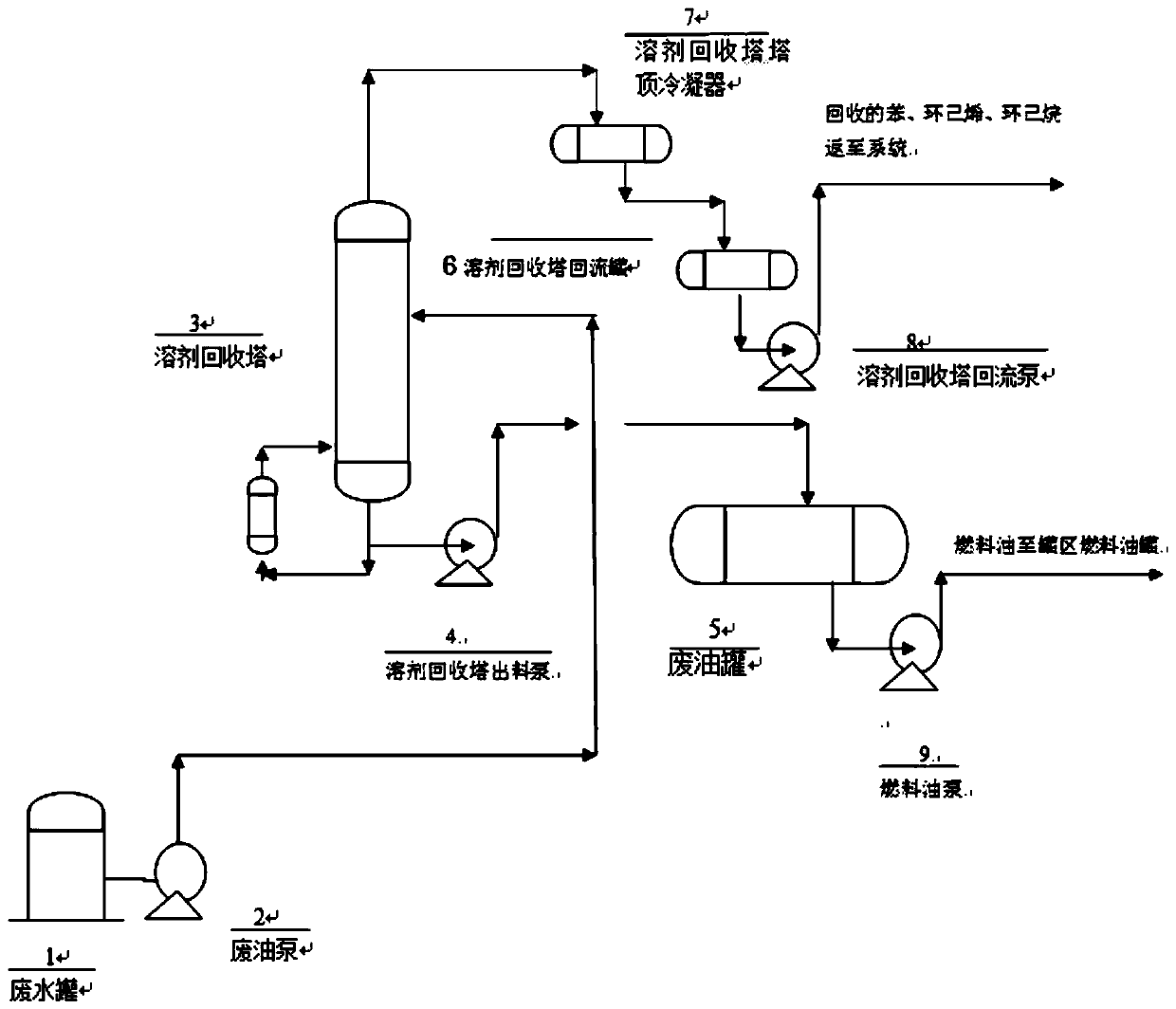
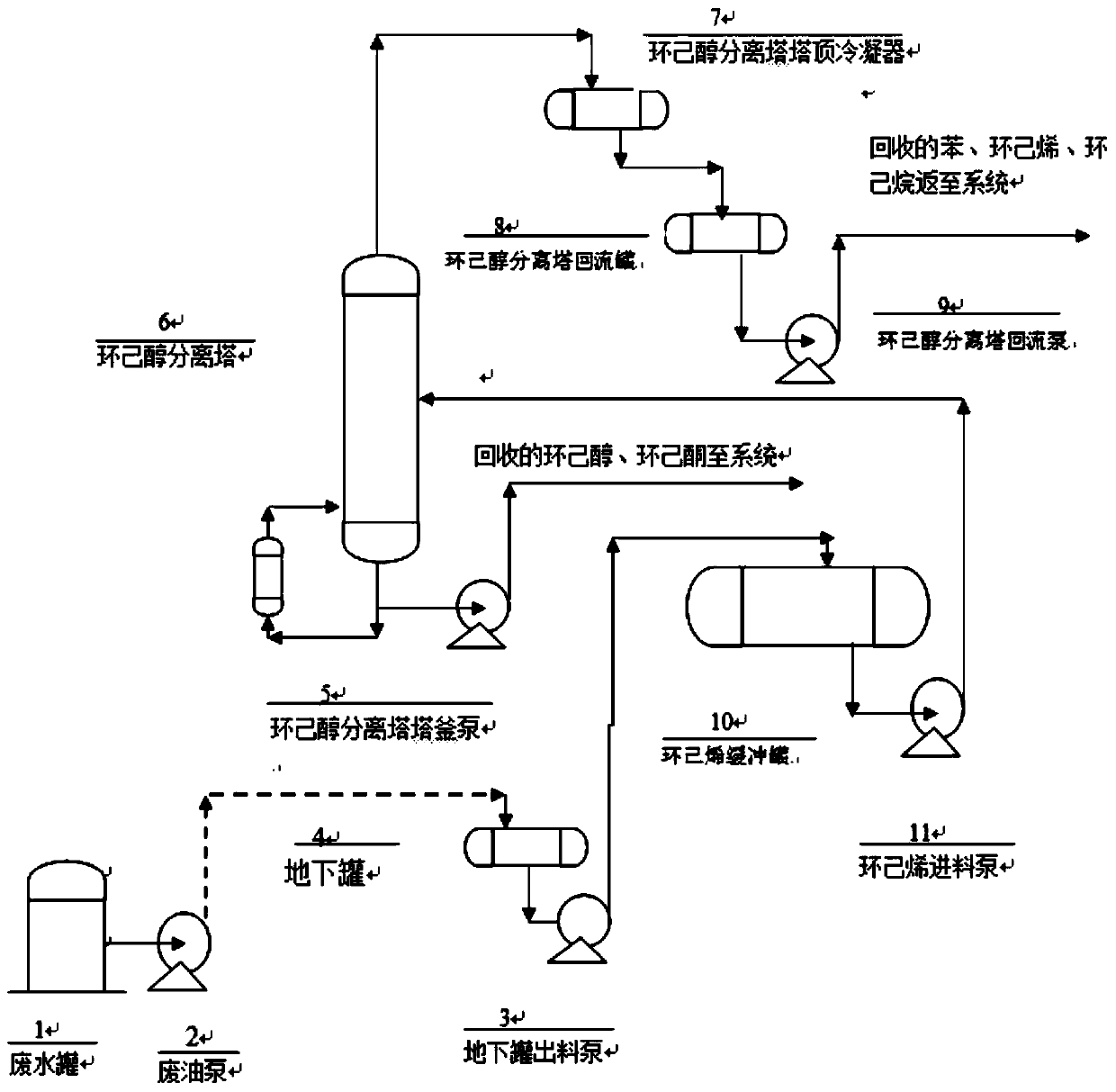
[0046] A pipeline is arranged between the waste oil pump 1 and the underground tank 4, and the waste oil and oily waste water recovered by the system is refined and stratified by the waste oil tank 1, and then transported to the underground tank 4 by the waste oil pump 2, and transported by the underground pump 3 In the cyclohexene buffer tank 10, the cyclohexanol separation tower feed pump 11 is transported to the cyclohexanol separation tower 6 by the cyclohexanol separation tower 6 inlet pipeline, and the effect of the cyclohexanol separation tower 6 is to remove waste oil The cyclohexanol contained in the heavy component enters the bottom of the cyclohexanol separation tower 6, and is separated and recycled after entering the refining system through the tower pump. The benzene, cyclohexene, and cyclohexane in the light component are separated by cyclohexanol After being condensed by the cyclohexanol separation tower condenser 7 at the top of the tower 6, it is recycled to t...

Embodiment 2

[0056] A fuel oil recovery system, comprising: waste water tank 1, waste oil pump 2, underground tank 4, underground pump 3, cyclohexene buffer tank 10, cyclohexene feed pump 11, cyclohexanol separation tower 6, condenser 7 , cyclohexanol separation tower reflux tank 8, cyclohexanol separation tower reflux pump 9, the waste water tank 1, waste oil pump 2, underground tank 4, underground pump 3, cyclohexene buffer tank 10, cyclohexene feed pump 11, cyclohexanol separation tower 6 is connected successively, and the tower top outlet of described cyclohexanol separation tower 6 is connected with condenser 7, and described condenser 7 is connected with cyclohexanol separation tower reflux tank 8, cyclohexanol separation tower reflux The pump 9 is connected; the bottom outlet of the cyclohexanol separation tower 6 is connected with the cyclohexanol and cyclohexanone recovery system through the cyclohexanol separation tower bottom pump 5.

[0057] The cyclohexanol separation tower 6 ...

Embodiment 3

[0059] A fuel oil recovery system, comprising: waste water tank 1, waste oil pump 2, underground tank 4, underground pump 3, cyclohexene buffer tank 10, cyclohexene feed pump 11, cyclohexanol separation tower 6, condenser 7 , cyclohexanol separation tower reflux tank 8, cyclohexanol separation tower reflux pump 9, the waste water tank 1, waste oil pump 2, underground tank 4, underground pump 3, cyclohexene buffer tank 10, cyclohexene feed pump 11, cyclohexanol separation tower 6 is connected successively, and the tower top outlet of described cyclohexanol separation tower 6 is connected with condenser 7, and described condenser 7 is connected with cyclohexanol separation tower reflux tank 8, cyclohexanol separation tower reflux The pump 9 is connected; the bottom outlet of the cyclohexanol separation tower 6 is connected with the cyclohexanol and cyclohexanone recovery system through the cyclohexanol separation tower bottom pump 5.

[0060] Waste oil and oily waste water are r...


PUM


Abstract

The invention relates to a fuel oil recovery system. The system comprises: a waste water tank, a waste oil pump, an underground tank, an underground pump, a cyclohexene buffer tank, a cyclohexene feeding pump, a cyclohexanol separation tower, a condenser, a cyclohexanol separation tower reflux tank, and a cyclohexanol separation tower reflux pump, wherein the waste water tank, the waste oil pump,the underground tank, the underground pump, the cyclohexene buffer tank, the cyclohexene feeding pump, and the cyclohexanol separation tower are connected in sequence, a tower top outlet of the cyclohexanol separation tower is connected with the condenser, the condenser is connected with the cyclohexanol separation column reflux tank and the cyclohexanol separation tower reflux pump, and a tower bottom outlet of the cyclohexanol separation tower is connected with a cyclohexanol and cyclohexanone recovery system through a tower kettle pump of the cyclohexanol separation tower. The process routeis changed, and the active components in a fuel oil are all recovered, so that the generation of an oily wastewater due to the cooking of the tower before and after the recovery by using a T1 solventrecovery tower is effectively avoided.

Description

technical field [0001] The invention belongs to an environment-friendly hazardous waste recycling process in the chemical industry, which mainly aims at recycling the hazardous waste fuel oil produced by caprolactam cyclohexanol to the system, so as to achieve the maximum utilization of resources, avoid resource reuse, waste resources, affect the environment, and cause waste. Background technique [0002] A large amount of fuel oil is produced during the production of cyclohexanol, and the fuel oil is sold as hazardous waste. The fuel oil mainly comes from the waste oil generated by system equipment pouring and dripping, running, emitting, dripping and leaking, and oil entrained in waste water. The main components of this part of waste oil are: cyclohexane 52%, cyclohexene 24%, benzene 21%, light components 0.9%, cyclohexanol 1.5%, and heavy components 0.6%, among which cyclohexane, cyclohexene, benzene, cyclohexanol and other components about 99% are the active components o...

Claims


Application Information

Patent Timeline
Patent Type & Authority Applications(China)
IPC IPC(8): C07C7/00C07C7/04C07C13/18C07C13/20C07C15/04C07C29/76C07C29/80C07C35/08
CPCC07C7/005C07C7/04C07C29/76C07C29/80C07C2601/16C07C2601/14C07C13/18C07C15/04C07C35/08Y02P20/10
Inventor 魏传国刘福青蒋加新丁凡常凤超张恒浩李兵高磊郭平彭康
Owner LIAOCHENG MEISI NEW MATERIAL TECH CO LTD
Why Eureka
Try Eureka