
A device and method for testing the separation performance of aircraft external stores in a high-speed wind tunnel

A high-speed wind tunnel and separation performance technology, which is applied in the field of high-speed wind tunnel experiments and flight mechanics, can solve the problems of difficult installation and adjustment, increase the degree of blockage of the wind tunnel, and reduce the degree of blockage of the wind tunnel. The effect of clogging degree and clogging degree reduction

Active Publication Date: 2021-10-29
RIZHAO KUNLUN INTELLIGENT TECH CO LTD
View PDF9 Cites 0 Cited by
  • Summary
  • Abstract
  • Description
  • Claims
  • Application Information

AI Technical Summary

Problems solved by technology

The three angle drives, control and detection equipment in the wind tunnel also increase the degree of blockage of the wind tunnel
In addition, the special installation and commissioning of this equipment will also allow the wind tunnel to have a longer time for stopping the blowing and parking preparations, reducing the blowing efficiency of the wind tunnel
[0006] CN104931222B discloses a machine-bomb separation trajectory capture test system. Compared with the above-mentioned scheme, although this patent has the advantages of higher rigidity and lower wind tunnel blockage, it still has the following disadvantages: First, the front end of the connecting rod of this scheme It is connected to the six-claw arm through a ball hinge, and the six-claw arm is rigidly connected to the tail rod. This scheme is compatible with the published six-bar parallel mechanism, such as 6-SPS (see Figure 5 ), 6-RSS (see Image 6 ) and Stewart parallel mechanism (see Figure 7 ) similarly, since the six ball hinges at the front ends of the six connecting rods are in the same plane and the plane is perpendicular to the airflow, in order to ensure sufficient rigidity of the tail strut, there needs to be enough space between the six ball hinges at the front ends of the six connecting rods Therefore, the rigidity of the tail strut can only be ensured by increasing the arm length of the six-claw arm, which will cause additional blockage in the wind tunnel, and this blockage appears near the maximum cross-section of the parent model. The increase in the above blockage would make transonic experiments more difficult
In addition, according to the size of the separated body model, the width of the six-claw arm also needs to be changed accordingly to meet the needs of supporting stiffness. In this way, different six-claw arms need to be replaced, which increases the preparation time and repeatability error of the wind tunnel
Second, the six linear actuators of this scheme are installed outside the wind tunnel test section, and six long slots are opened on the wall of the wind tunnel test section to connect with the ball hinge at one end of the connecting rod in the wind tunnel test section. , Adjustment is difficult, and the long groove of the wind tunnel test section will seriously damage the original structure of the wind tunnel test section, so that a special wind tunnel test section needs to be customized
Third, since the six linear actuators of this scheme must be placed within the resident range of the wind tunnel test section, the additional blockage is superimposed on the blockage of the parent model and the angle of attack mechanism, which increases the difficulty of the transonic experiment

Method used


Image

  • A device and method for testing the separation performance of aircraft external stores in a high-speed wind tunnel
  • A device and method for testing the separation performance of aircraft external stores in a high-speed wind tunnel
  • A device and method for testing the separation performance of aircraft external stores in a high-speed wind tunnel

Examples


Embodiment Construction

[0072] In order to clearly illustrate the technical features of this solution, the specific implementation of the present invention will be further described below according to the accompanying drawings.

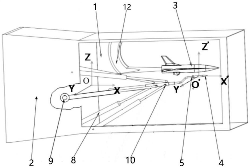
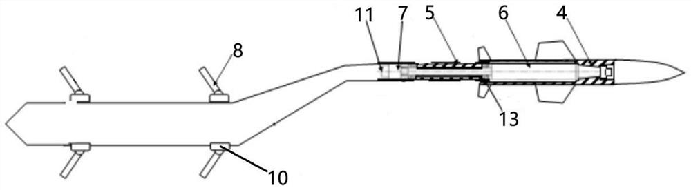
[0073] Such as figure 1 and figure 2 As shown, a device for testing the separation performance of aircraft external stores in a high-speed wind tunnel, including a wind tunnel experiment section 1, a wind tunnel diffusion section 2, a parent aircraft model 3, an external store model 4, a tail strut 5, a digital displacement cylinder 8, Multi-component balance 6, rolling drive device 7, rolling measuring device 11 and position measuring device.

[0074] The parent aircraft model 3 is an aircraft model that carries the external store model 4 and is used to test the separation performance of the external store model 4. The parent aircraft model 3 is installed inside the wind tunnel test section 1 through the variable angle of attack device 12. The variable angle of attack de...


PUM


Abstract

The invention belongs to the technical field of high-speed wind tunnel experiments and flight mechanics, and in particular relates to a device for testing the separation performance of external objects of an aircraft in a high-speed wind tunnel, comprising a wind tunnel experiment section, a wind tunnel diffusion section, a parent aircraft model, an external object model, and a tail branch Rod and digital displacement cylinder, there are multi-component balances in the external store model, and a rolling drive device is provided in the tail support rod, the output shaft of the rolling drive device is connected to the multi-component balance; there are six digital displacement cylinders, and the digital displacement The rear end of the cylinder is connected to the rear of the wind tunnel test section or the front of the wind tunnel diffusion section through the rear ball hinge, and the front end of the digital displacement cylinder is connected to the tail rod through the front ball hinge; the displacement of the digital displacement cylinder can realize the The movement, pitch and yaw of the model, and the roll drive device can drive the store model to roll. The invention also provides a method for testing the separation performance of the external stores of the aircraft. The invention can ensure sufficient rigidity of the tail strut and reduce the clogging degree of the wind tunnel as much as possible.

Description

technical field [0001] The invention belongs to the technical field of high-speed wind tunnel experiments and flight mechanics, and in particular relates to a device and method for testing the separation performance of aircraft external stores in a high-speed wind tunnel. Background technique [0002] During the flight phases such as launch or release of aircraft external stores, and separation between spacecraft stages, especially the initial separation stage, the external stores and the parent aircraft are very close, and the speed is similar, and the external stores and the parent aircraft are in a complex mutual interference flow field. Poor separation characteristics will not only affect the flight accuracy of the external store, but even lead to a collision with the parent aircraft, endangering flight safety. Similar accidents have occurred many times in the past development history. Therefore, it is very necessary to understand the separation process and the dynamic ...

Claims


Application Information

Patent Timeline
Patent Type & Authority Patents(China)
IPC IPC(8): G01M9/02G01M9/06
CPCG01M9/02G01M9/06
Inventor 黄兴中
Owner RIZHAO KUNLUN INTELLIGENT TECH CO LTD
Learn More