
A kind of preparation method of oled device

A technology for a device and an etching barrier layer, which is applied in the field of preparation of OLED devices, can solve the problems affecting the display effect of the OLED device, the calculation of the thickness of the microcavity is complicated, the damage of the first insulating layer, etc., to achieve good optical effects and improve the etching efficiency The effect of high rate and etching ratio

Active Publication Date: 2022-03-25
SEEYA OPTRONICS LTD
View PDF5 Cites 0 Cited by
  • Summary
  • Abstract
  • Description
  • Claims
  • Application Information

AI Technical Summary

Problems solved by technology

But its effect still has unsatisfactory place, first, the material of the second insulating layer and the third insulating layer are the same, there is no etch ratio between the two, when the first patterned photoresist is used as a mask to etch the first In the case of three insulating layers, the requirements for the etching process are very high, and it is very likely that the third insulating layer is not etched clean or the process of the second insulating layer is damaged by over-etching; moreover, although the first insulating layer and the second insulating layer The materials of the two insulating layers are different, and there is an etching ratio, but the material properties of silicon nitride and silicon oxide are relatively close, and the etching ratio is less than 10:1, that is, every ten units of silicon oxide etched will consume more than one unit. Silicon nitride, when etching the second insulating layer, there is still a lot of damage to the first insulating layer; third, the optical adjustment layer is formed of different materials, the refractive index of silicon nitride is about 1.8, and the refractive index of silicon oxide In 1.4, the light will be refracted at the interface between the two, which will make the calculation of the thickness of the microcavity more complicated, light pollution and other uncertain optical problems will also increase, greatly affecting the display effect of OLED devices

Method used


Image

  • A kind of preparation method of oled device
  • A kind of preparation method of oled device
  • A kind of preparation method of oled device

Examples


preparation example Construction

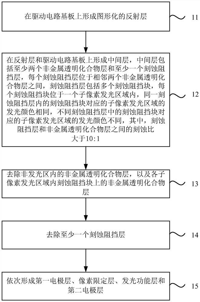
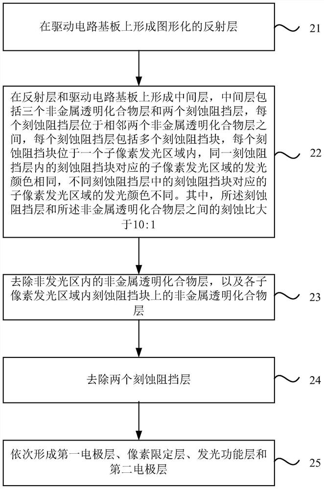
[0028] An embodiment of the present invention provides a method for preparing an OLED device, including:

[0029] forming a patterned reflective layer on the driving circuit substrate;

[0030] An intermediate layer is formed on the reflective layer and the driving circuit substrate, the intermediate layer includes at least two non-metallic transparent compound layers and at least one etching barrier layer, each of the etching barrier layers is located in two adjacent ones between the non-metallic transparent compound layers; the etching stopper layer includes a plurality of etching stopper blocks, each of the etching stopper blocks is located in a sub-pixel light-emitting area, and all the etching stopper blocks in the same etching stopper layer are The light-emitting colors of the sub-pixel light-emitting regions corresponding to the etching blocking blocks are the same, and the light-emitting colors of the sub-pixel light-emitting regions corresponding to the etching blocki...


PUM

PropertyMeasurementUnit
thicknessaaaaaaaaaa
thicknessaaaaaaaaaa
refractive indexaaaaaaaaaa

Abstract

The invention discloses a method for preparing an OLED device, comprising: forming a reflective layer; forming an intermediate layer, the intermediate layer includes at least two non-metallic transparent compound layers and at least one etching barrier layer, each etching barrier layer is located on two adjacent Between two non-metallic transparent compound layers; the etch barrier layer includes a plurality of etch barrier blocks, each etch barrier block is located in a sub-pixel light-emitting area, and the corresponding sub-pixel of the etch barrier block in the same etch barrier layer The luminous colors of the light-emitting regions are the same, and the luminous colors of the sub-pixel light-emitting regions corresponding to the etching barrier blocks in different etching barrier layers are different; remove the non-metallic transparent compound layer in the non-light-emitting region, and etch The non-metallic transparent compound layer on the barrier block; removing the etching barrier layer; forming the first electrode layer, the pixel definition layer, the light-emitting functional layer and the second electrode layer; wherein, the etching barrier layer and the non-metallic transparent compound layer The etch ratio is greater than 10:1.

Description

technical field [0001] The embodiments of the present invention relate to a preparation technology of an OLED device, and in particular, to a preparation method of an OLED device. Background technique [0002] OLED devices have the advantages of self-luminescence, low power consumption and wide color gamut, and are favored by users. [0003] In the prior art, the OLED device adopts a microcavity structure to improve the luminous intensity, and the strong microcavity structure is a conventional microcavity structure. Specifically, the OLED device includes a reflective layer, a transparent compound layer, a first electrode layer, a light-emitting functional layer, and a second electrode layer sequentially stacked on a driving circuit substrate. The surface on the side of the circuit substrate, and the surface on the side of the second electrode layer close to the drive circuit substrate. Generally, when the thickness of the microcavity in the light-emitting region of each su...

Claims


Application Information

Patent Timeline
Patent Type & Authority Patents(China)
IPC IPC(8): H01L51/56
CPCH10K71/00
Inventor 张建军居宇涵
Owner SEEYA OPTRONICS LTD
Learn More