Circularly polarized microstrip patch antenna

A technology of microstrip patch antenna and circular polarization, which is applied in the direction of antenna, antenna grounding device, antenna support/installation device, etc., and can solve the problems of narrow working bandwidth of microstrip antenna, unsuitable application, and increased antenna size , to achieve the effect of convenient industrial processing, light weight and wide gain bandwidth

Pending Publication Date: 2019-08-27
江苏三和欣创通信科技有限公司
View PDF0 Cites 4 Cited by
  • Summary
  • Abstract
  • Description
  • Claims
  • Application Information

AI Technical Summary

Problems solved by technology

[0005] 1. Ordinary microstrip antennas generally implement a single-layer medium to achieve a working frequency band. This kind of working bandwidth is relatively narrow, and the working bandwidth is only about 5%. It cannot be well applied in ultra-wideband (spread spectrum) communication systems.
If the bandwidth is increased, it is often necessary to use a medium with a low dielectric constant as the antenna substrate material, and the antenna size will increase at this time
[0006] 2. Conventional helical antennas have good frequency bandwidth, beam width, symmetric pattern, and wide-angle circular polarization. The disadvantage is that only one polarization mode can be realized.
In the case where dual circular polarization is required, the application cannot be satisfied
[0007] 3. Array antenna (or element deformation), frequency bandwidth, symmetric pattern, wide-angle circular polarization performance is good, the disadvantage is that the beam is not wide enough, the structure is more complicated, and the size is larger
However, the working bandwidth of the traditional microstrip antenna is relatively narrow, generally 3%-5%, which cannot be used in spread spectrum communication.

Method used


Image

  • Circularly polarized microstrip patch antenna
  • Circularly polarized microstrip patch antenna
  • Circularly polarized microstrip patch antenna

Examples


Embodiment 1

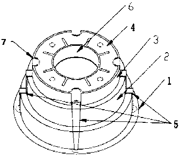
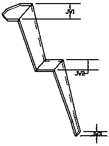
[0047] Such as Figure 1-3 As shown, a circularly polarized microstrip patch antenna includes: a conductive ground plane 1, a dielectric substrate disposed on the conductive ground plane, a radiation sheet 4 disposed on the top of the dielectric substrate, and a dielectric substrate disposed on the surrounding sides Several feeding probes 5 of the wall;

[0048] The dielectric substrate includes a lower dielectric substrate 2 with a high dielectric constant and an upper dielectric substrate 3 with a low dielectric constant; by adjusting the dielectric constants and thicknesses of different materials, different operating frequencies, gains and operating bandwidths can be obtained.

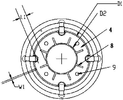
[0049] The radiation piece 4 is a thin circular metal conductor, and a gear-shaped opening 8 with a symmetrical structure is processed in the middle of the radiation piece for receiving or transmitting signals. figure 2 Among them, the outer diameter D1, inner diameter D2, serrated length L1, and wi...

Embodiment 2

[0060] Such as Figure 4 , shows an antenna gain bandwidth test chart of the circularly polarized microstrip patch antenna in Embodiment 1.

[0061] Such as Figure 5 , shows an antenna axial ratio test diagram of the circularly polarized microstrip patch antenna in Embodiment 1.

[0062] Such as Image 6 , shows a center frequency point beam width test diagram of the circularly polarized microstrip patch antenna in Embodiment 1.

[0063] It can be seen that the circularly polarized antenna device in Embodiment 1 has the characteristics of large axial ratio bandwidth, wide working bandwidth, and stable phase center.

Embodiment 3

[0065] Such as Figure 7 , using 4 orthogonal feeding probes, every two adjacent ones undergo signal phase shifting, and obtain good left-handed and right-handed circularly polarized signal outputs after combining. (Hybrid is a coupler with a phase shift of 90 degrees).

[0066] With four feeding probes, the loss of the feeding circuit is large, but the circular polarization performance is good, and the antenna is symmetrical, so that the phase center is stable.


PUM


Abstract

The invention discloses a circularly polarized microstrip patch antenna. The antenna comprises a conductive grounding plane, a dielectric substrate arranged on the conductive grounding plane, a radiation sheet arranged at the top of the dielectric substrate and a plurality of feed probes arranged on the side walls of the periphery of the dielectric substrate; the dielectric substrate comprises a lower-layer high-dielectric-constant dielectric substrate and an upper-layer low-dielectric-constant dielectric substrate; the radiation sheet is a sheet-shaped circular metal conductor; and a gear-shaped opening of a symmetrical structure is formed in the middle of the radiation sheet. A gradient folding type side coupled feed mode is adopted; the feed probes are gradually bent; the processing issimple; relatively wide bandwidth is easily formed; the circular polarization performance of the antenna is improved; the phase center is stable; right-handed and left-handed circular polarization canbe realized at the same time; the antenna is especially suitable for accurate measurement and guidance system terminal equipment; the two dielectric substrates with different dielectric constants areadopted; and the designed antenna is small in size, light in weight and wide in gain bandwidth which can reach more than 25%.

Description

technical field [0001] The invention belongs to the technical field of antennas, and in particular relates to a circularly polarized microstrip patch antenna. Background technique [0002] As a component used to transmit or receive radio waves, circularly polarized antennas play a vital role in wireless communication systems, especially in satellite communications and aircraft measurement and control equipment. [0003] The current satellite navigation and positioning equipment is widely used in fields such as positioning, measurement, timing, high-precision agriculture and intelligent transportation. In order to obtain high-precision positioning requirements above the decimeter level, navigation equipment generally adopts RTK (real-time dynamic differential method) technology. And axle ratio bandwidth), and more compact size, while processing and manufacturing should be simple. Due to the advantages of small shape, low cost, easy conformality, easy processing and easy rea...

Claims


Application Information

Patent Timeline
Patent Type & Authority Applications(China)
IPC IPC(8): H01Q1/12H01Q1/28H01Q1/38H01Q1/48H01Q1/50H01Q15/24
CPCH01Q1/12H01Q1/28H01Q1/38H01Q1/48H01Q1/50H01Q15/24
Inventor 施静李庚禄华娟刘兆吴艳杰李铎张慧龙
Owner 江苏三和欣创通信科技有限公司
Why Eureka
Try Eureka