
An onboard airtight cooling conduction chassis

It is a closed and airborne technology, which is applied in the directions of sealed enclosure, cooling/ventilation/heating modification, support structure installation, etc. It can solve the problems of high integration, high heat generation, and inability to meet the heat dissipation problems of high-power electronic equipment modules. Achieve the effect of improving heat dissipation efficiency and ensuring stability

Active Publication Date: 2020-07-03
BEIJING INST OF RADIO MEASUREMENT
View PDF5 Cites 0 Cited by
  • Summary
  • Abstract
  • Description
  • Claims
  • Application Information

AI Technical Summary

Problems solved by technology

At present, due to the high integration of electronic equipment in the airborne chassis and the large heat generated by a single electronic equipment module, the simple use of conduction cooling plus secondary air cooling can no longer meet the heat dissipation problem of high-power electronic equipment modules, and new considerations need to be considered. The structural form to enhance the cooling capacity of the airborne chassis

Method used


Image

  • An onboard airtight cooling conduction chassis
  • An onboard airtight cooling conduction chassis
  • An onboard airtight cooling conduction chassis

Examples


Embodiment

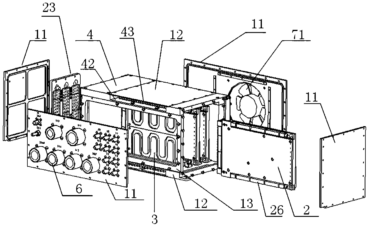
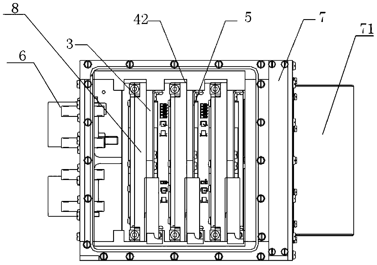
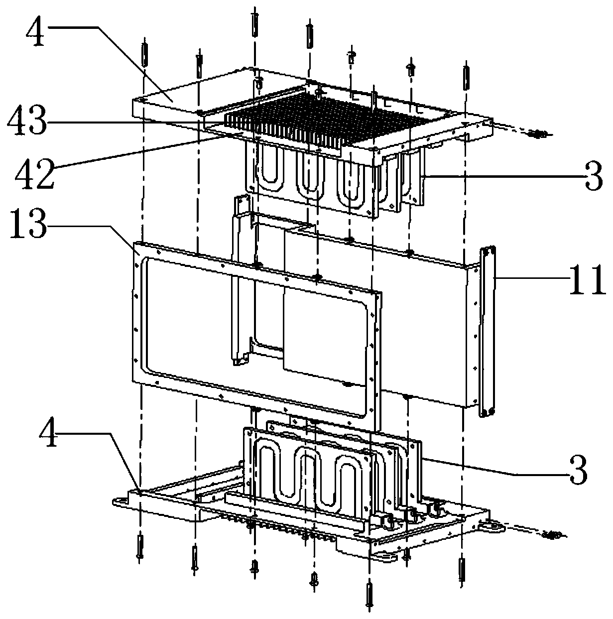
[0038] Such as figure 1 and figure 2 As shown, an airborne airtight cooling conduction chassis of this embodiment includes a box body 1, an electronic plug-in 2, a heat pipe module 3, a cold plate 4, a connecting plate 11, a heat pipe module 3, an air chamber 7, and a fan 71 , nut bar 21, mounting piece 22, motherboard 23, fixing plate 5, IO connection assembly 6, cover plate 12, one of which connecting plate 11 is between two oppositely arranged cold plates 4, and divides the box body 1 into mutually different Connected electrical cavity 8 and cavity 7; a number of heat pipe modules 3 are integrally connected to the inner wall of the cold plate 4, and the electrical cavity 8 is divided into several insertion channels for installing electronic plug-ins 2, and the two cold plates 4 are oppositely arranged and the heat pipe module 3 on it is correspondingly abutted; the inner concave surface 42 on the outer wall of the cold plate 4 is provided with a number of cooling fins 43,...


PUM


Abstract

The invention relates to an airborne closed cold guide machine box. The airborne closed cold guide machine box comprises a box body, electronic connectors and heat pipe modules, wherein an internallysealed electric cavity encircled by a cold plate and a connecting plate is formed in the box body; the inner side wall of the cold plate is integrally connected with a plurality of heat pipe modules so that the electric cavity is partitioned into a plurality of inserting passages for mounting the electronic connectors; the electronic connectors are in contact with the heat pipe modules, heat dissipation air flues and an air cavity communicating with the heat dissipation air flues are formed in the positions, corresponding to the joints of the heat pipe modules, on the outer side wall of the cold plate, and the air cavity is connected with a draught fan; on the basis of guaranteeing the airtightness of the electric cavity, due to the fact that the heat pipe modules and the electronic connectors are in one-to-one correspondence so that the contact area is increased, the heat is quickly transferred onto the cold plate through the heat pipe modules, and then the heat is discharged throughthe air cavity by the draught fan; and moreover, the heat pipe modules also can be used for carrying out uniform temperature heat dissipation on a concentrated heat source, so that the heat dissipation efficiency of the airborne closed cold guide machine box is improved greatly.

Description

technical field [0001] The invention relates to an airborne chassis, in particular to an airborne airtight cooling conduction chassis with high heat dissipation efficiency. Background technique [0002] Due to the operating environment of the bodywork aircraft, the airborne chassis must be able to withstand harsh environments such as rain, fluid pollution, sand and dust, strong vibrations, etc. In order to avoid being affected by the harsh airborne environment, the airborne chassis must adopt a sealed structure. At present, due to the high integration of electronic equipment in the airborne chassis and the large heat generated by a single electronic equipment module, the simple use of conduction cooling plus secondary air cooling can no longer meet the heat dissipation problem of high-power electronic equipment modules, and new considerations need to be considered. The structural form is to enhance the heat dissipation capacity of the airborne chassis. [0003] Therefore, h...

Claims


Application Information

Patent Timeline
Patent Type & Authority Patents(China)
IPC IPC(8): H05K7/20H05K5/06H05K7/14
CPCH05K5/06H05K7/1401H05K7/20145H05K7/20336H05K7/20409
Inventor 骆德军
Owner BEIJING INST OF RADIO MEASUREMENT
Learn More