Rapid cutter servo device with dynamic force balance function

A servo device and dynamic force technology, applied in the direction of manufacturing tools, metal processing machinery parts, maintenance and safety accessories, etc., can solve problems such as dynamic forces that are difficult to ignore, and achieve the effects of saving design space, improving efficiency, and compact volume

Pending Publication Date: 2019-08-30
JIANGSU JITRI JINGKAI HIGH VALUE MFG CO LTD
View PDF7 Cites 2 Cited by
  • Summary
  • Abstract
  • Description
  • Claims
  • Application Information

AI Technical Summary

Problems solved by technology

However, in the fast-knife servo device based on voice coil motor and air bearing, the quality of its moving part has been greatly improved compared with the fast-knife servo device based on piezoelectric ceramics and flexible mechanisms, so it produces dynamic forces that are difficult to ignore during the work process.

Method used


Image

  • Rapid cutter servo device with dynamic force balance function
  • Rapid cutter servo device with dynamic force balance function

Examples


Embodiment Construction

[0020] The present invention will be described in detail below in conjunction with the accompanying drawings.

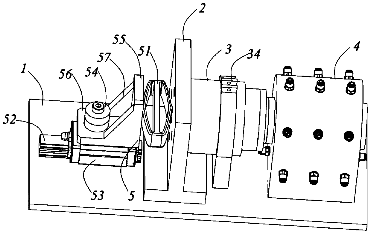
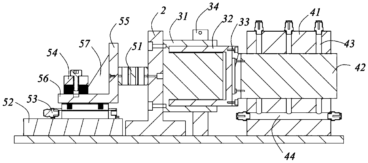
[0021] Such as figure 1 and figure 2 A fast tool servo device with dynamic force balance function is shown, including a base 1 arranged on the machine tool, a motor assembly 3 arranged on the base 1, a first guide rail assembly 4 arranged on the motor assembly 3, and a first guide rail assembly 4 arranged on the first The tool on the guide rail assembly 4 is fixed with a connector 2 on the base 1, the motor assembly 3 is fixed on one side of the connector 2, and the other side of the connector 2 is provided with a balance The motor assembly 3 moves a balance assembly 5 that generates dynamic force. The movement of the motor assembly 3 causes the tool on the first guide rail assembly 4 to move to realize the machining of the workpiece by the tool. Due to the dynamic force generated by the movement of the motor assembly 3, a balance assembly 5 is provided on the oth...


PUM


Abstract

The invention relates to a rapid cutter servo device with a dynamic force balance function. The rapid cutter servo device comprises a base arranged on a machine tool, a motor assembly arranged on thebase, a first guide rail assembly arranged on the motor assembly, and a cutter arranged on the first guide rail assembly. A connecting piece is fixed to the base. The motor assembly is fixed to one side of the connecting piece, and the other side of the connecting piece is provided with a balance assembly for balancing the dynamic force generated during the motion of the motor assembly. By means of the rapid cutter servo device, the balance of the dynamic force generated by a motion part of the rapid cutter servo device in the work state is achieved, and the optics non-rotational symmetric hook face machining precision can be effectively improved; and meanwhile, the dynamic force balance assembly is simple in structure and convenient to install, the design space is greatly saved, the sizeof the rapid cutter servo device in which the dynamic force balance assembly is added is more compact, accordingly, the assembling difficulty of the rapid cutter servo device in the limited space of the machine tool is lowered, and efficiency is improved.

Description

technical field [0001] The invention belongs to the technical fields of ultra-precision turning and turning of optical precision parts, and relates to a fast knife servo device with a dynamic force balance function. Background technique [0002] Optical non-rotational symmetric surfaces refer to optical free-form surfaces without rotational symmetry axes. Compared with traditional symmetric optical elements, optical non-rotational symmetric surfaces combine complex free-form surfaces into an optical system, which can not only greatly eliminate light Negative effects in the transfer process, such as astigmatism, distortion and coma, can also effectively reduce the loss of light energy. The excellent optical performance not only makes it widely used in aerospace exploration, aerospace and national defense, but also in industrial fields, such as automobile manufacturing, ophthalmic optical lenses, digital cameras and other fields. In order to achieve high-efficiency mass produ...

Claims


Application Information

Patent Timeline
Patent Type & Authority Applications(China)
IPC IPC(8): B23Q11/00
CPCB23Q11/0035
Inventor 滕翔宇霍德鸿丁辉
Owner JIANGSU JITRI JINGKAI HIGH VALUE MFG CO LTD
Why Eureka
Try Eureka