Invisible structure of anchor bar and application of invisible structure

An anchor bar and invisible technology, applied in the direction of building construction, construction, etc., can solve the problems of increased workload, difficulty in withdrawing formwork, damage, etc., to eliminate damage and repair process, enhance the appearance of concrete surface, and speed up the turnover speed Effect

Pending Publication Date: 2019-08-30
广东振港工程有限公司 +4
View PDF0 Cites 0 Cited by
  • Summary
  • Abstract
  • Description
  • Claims
  • Application Information

AI Technical Summary

Problems solved by technology

This will bring about two problems. The first problem is that holes need to be drilled in the standard formwork, which is not conducive to the later use of the formwork; will damage the template
This complex and unfavorable situation is more common in the construction of gate slots. For example, in the construction of sluice pier, shaped steel formwork or shaped wooden formwork is generally used for installation. Anchoring steel bars with a diameter of about 18 to 20mm are pre-embedded on the front and inner sides (the design generally protrudes 30cm), and the anchoring steel bars are used to overlap with the second-stage concrete and gate rail; the traditional process needs to be pre-embedded in the formwork (design interval 0.5m) Drill holes and insert steel bars for reservation. The pre-embedded steel bars protrude about 10 to 30 cm outside the formwork. After the concrete gate groove is poured and tamped, the formwork is removed. ) in the two directions of the pre-buried (designed to protrude 30cm) anchor bars, which pass through the formwork and are anchored in the concrete. Therefore, when the formwork is removed, it is blocked by the embedded bars in the two directions of the concave steel formwork of the gate groove, and the formwork cannot be withdrawn. It is very different to cut the protruding steel bar short and withdraw it and then perform barge length welding, or shorten the length of the anchor bar protruding outside the formwork to 5 to 10 cm during pre-embedding, and then perform barge length welding after the formwork is removed. It is beneficial to formwork removal construction and greatly increases the workload. In addition, the original formwork will be damaged due to drilling. It is difficult to withdraw the formwork during formwork removal. Repeated formwork will be required, which will affect the construction progress and cost control. The holes in the perforation process will Lead to grout leakage, surface unevenness such as concrete pockmarks or honeycombs

Method used


Image

  • Invisible structure of anchor bar and application of invisible structure
  • Invisible structure of anchor bar and application of invisible structure
  • Invisible structure of anchor bar and application of invisible structure

Examples


Embodiment Construction

[0039] The technical solution of the present invention will be described in further detail below in conjunction with specific embodiments and accompanying drawings, but the protection scope of the present invention is not limited to the following specific embodiments.

[0040] It should be noted that, unless otherwise mentioned, the equipment used in the following examples can be purchased through commercial channels. For the sake of brevity, some conventional technical operations in this field are not described in detail, and these technical operations are generally performed according to conventional methods. It should be understood that those skilled in the art know the details of these technical operations and can reproduce them to achieve the final technical effect.

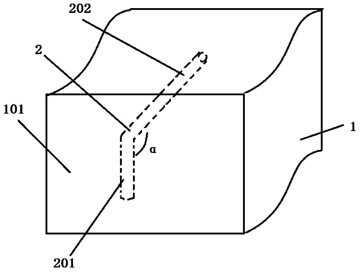
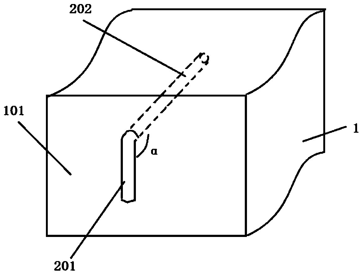
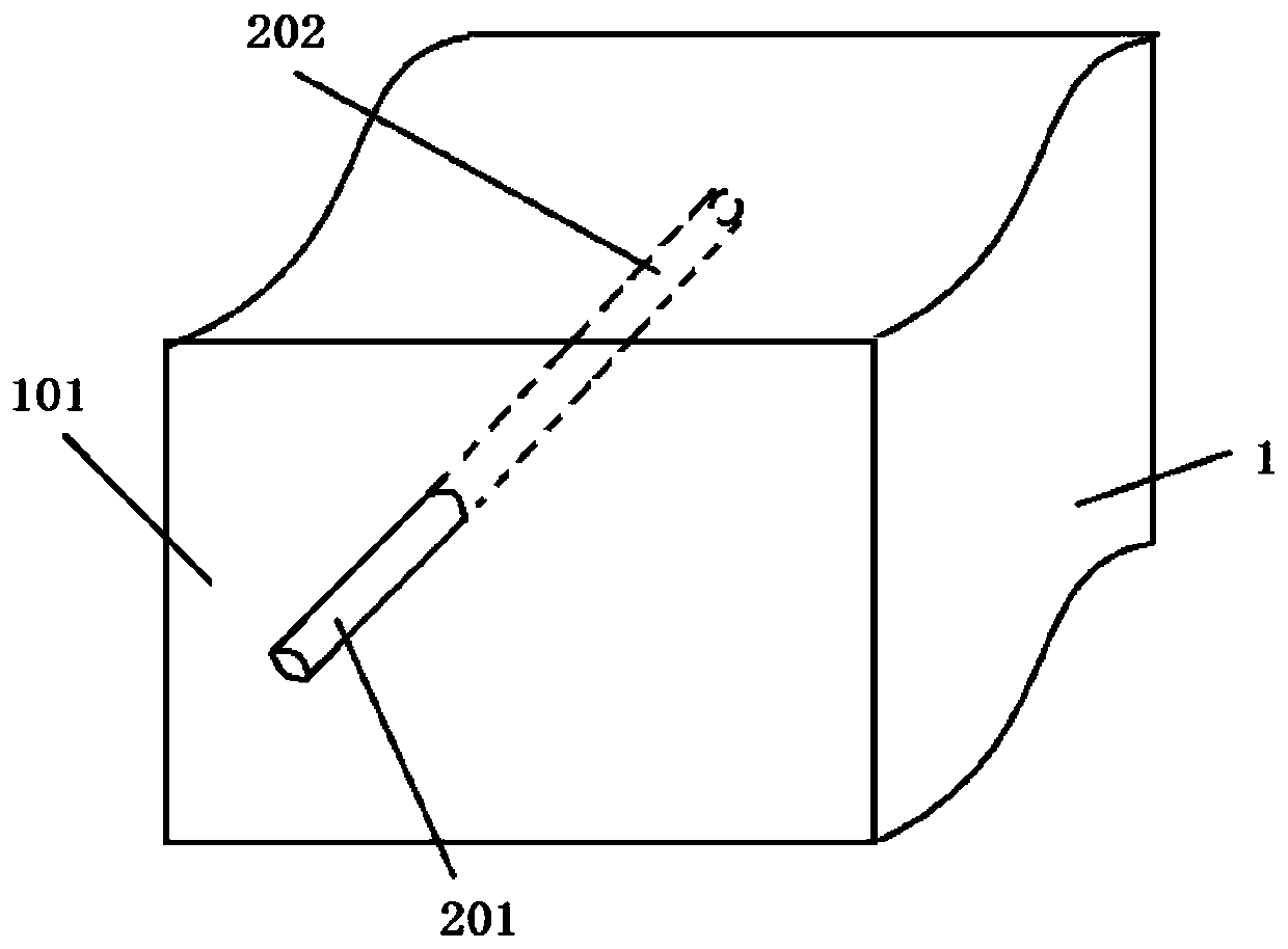
[0041] In the figure, the solid line shows the part that can be directly observed by the naked eye, and the dotted line shows the part hidden inside the structure that cannot be seen by the naked eye.

[004...


PUM


Abstract

The invention provides an invisible structure of an anchor bar. The invisible structure includes a base and an anchor bar, wherein the anchor bar is a complete steel bar, and includes a first segmentand a second segment; the first segment and the second segment form an included angle of 90 degrees; and the second segment of the anchor bar is embedded in the base, and the first segment is close toone surface of the base. According to the invisible structure of the anchor bar, no holes are required to be formed in formworks during concrete pouring vertical formwork construction, and the disassembly and assembly of the formworks are very convenient, materials are saved, and safety and high efficiency are achieved.

Description

technical field [0001] The invention belongs to the field of civil engineering, and in particular relates to an anchor bar invisible structure and application thereof. Background technique [0002] With the rapid development of national infrastructure construction, investment in water conservancy and hydropower projects has also continued to increase, and a large number of hydropower, river hubs, farmland water conservancy, urban flood control, and water supply and drainage projects have been built to benefit and eliminate disasters, reduce disasters, and improve The water environment plays a huge role in promoting the sustainable development of economy and society. [0003] In the hydraulic building structure that needs to pour the second-stage concrete or install related embedded parts, the traditional construction technology is to first open a hole at a predetermined position on the formwork, then insert and bury the linear anchor bar and then pour the concrete. Formwork...

Claims


Application Information

Patent Timeline
Patent Type & Authority Applications(China)
IPC IPC(8): E04B1/41
CPCE04B1/41E04B1/4171
Inventor 杨励昌赖翼峰段青梅杨志兴杨才兴杨振兴杨小辉杨雪傲苏良平
Owner 广东振港工程有限公司
Why Eureka
Try Eureka