Floating mechanism of reactor

A reactor and floating bucket technology, applied in the field of floating mechanisms, can solve problems such as troublesome operation, and achieve the effects of convenient adjustment, improved binding capacity and low cost

Active Publication Date: 2019-09-06
北京林源利景科技发展有限公司
View PDF4 Cites 0 Cited by
  • Summary
  • Abstract
  • Description
  • Claims
  • Application Information

AI Technical Summary

Problems solved by technology

[0003] The quantum wave reaction device is floating on the water surface, but the suspension height of the rack plate is closely related to the relationship between the floating bucket, so when it is necessary to adjust the suspension height of the rack plate in the later stage, the only way is to change the buoyancy of the floating bucket To adjust, the operation is more troublesome

Method used


Image

  • Floating mechanism of reactor
  • Floating mechanism of reactor
  • Floating mechanism of reactor

Examples


Embodiment 1

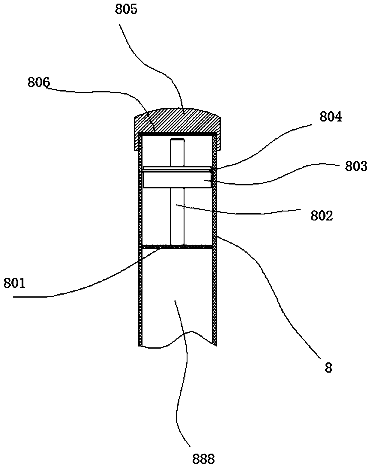
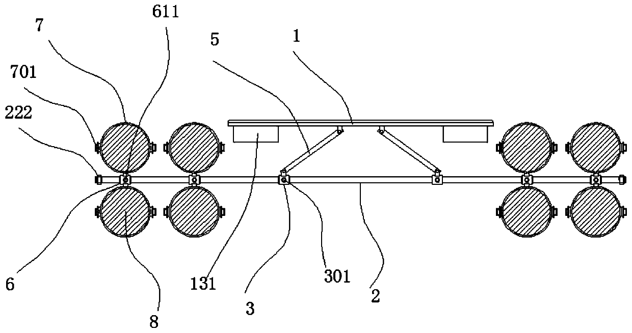
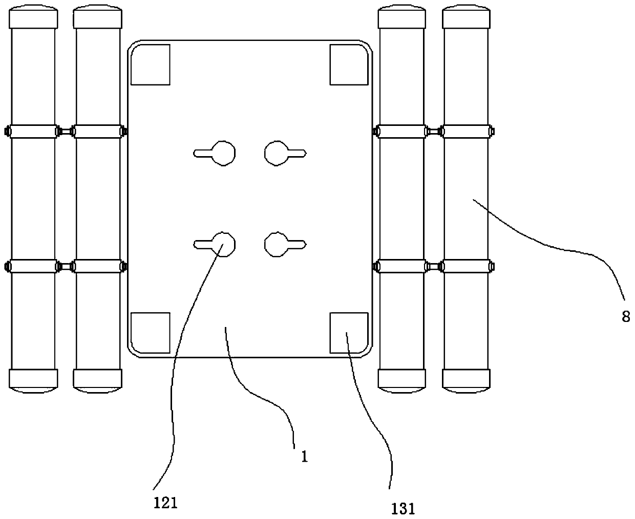
[0056] Such as figure 1 , figure 2 , image 3 with Figure 4 The floating mechanism of a reactor shown includes a frame plate 1, two horizontal rods 2 are arranged below the frame plate 1, and the two horizontal rods 2 are arranged in front and rear in parallel. Two sliding sleeves 3 are provided on each of the cross bars 2, a connecting rod 4 is welded between the front and rear sliding sleeves 3, and a screw 301 is fitted between the sliding sleeve 3 and the cross bar 2. A first connecting rod 5 is hinged between the frame plate 1 and the sliding sleeve 3, and a first sliding sleeve 6 is mounted on the cross bar 2. The upper and lower ends of the first sliding sleeve 6 are A ring body 7 for fixing is welded, a floating bucket 8 is installed between the ring bodies 7 on the front and rear sides, and a first screw 701 is installed between the ring body 7 and the floating bucket 8. A second screw 611 is installed between a sliding sleeve 6 and the cross bar 2, and a hole 121 fo...

Embodiment 2

[0063] Such as figure 1 , figure 2 , image 3 with Figure 4 The floating mechanism of a reactor shown includes a frame plate 1, two horizontal rods 2 are arranged below the frame plate 1, and the two horizontal rods 2 are arranged in front and rear in parallel. Two sliding sleeves 3 are provided on each of the cross bars 2, a connecting rod 4 is welded between the front and rear sliding sleeves 3, and a screw 301 is fitted between the sliding sleeve 3 and the cross bar 2. A first connecting rod 5 is hinged between the frame plate 1 and the sliding sleeve 3, and a first sliding sleeve 6 is mounted on the cross bar 2. The upper and lower ends of the first sliding sleeve 6 are A ring body 7 for fixing is welded, a floating bucket 8 is installed between the ring bodies 7 on the front and rear sides, and a first screw 701 is installed between the ring body 7 and the floating bucket 8. A second screw 611 is installed between a sliding sleeve 6 and the cross bar 2, and a hole 121 fo...

Embodiment 3

[0076] Such as figure 1 , figure 2 , image 3 with Figure 4 The floating mechanism of a reactor shown includes a frame plate 1, two horizontal rods 2 are arranged below the frame plate 1, and the two horizontal rods 2 are arranged in front and rear in parallel. Two sliding sleeves 3 are provided on each of the cross bars 2, a connecting rod 4 is welded between the front and rear sliding sleeves 3, and a screw 301 is fitted between the sliding sleeve 3 and the cross bar 2. A first connecting rod 5 is hinged between the frame plate 1 and the sliding sleeve 3, and a first sliding sleeve 6 is mounted on the cross bar 2. The upper and lower ends of the first sliding sleeve 6 are A ring body 7 for fixing is welded, a floating bucket 8 is installed between the ring bodies 7 on the front and rear sides, and a first screw 701 is installed between the ring body 7 and the floating bucket 8. A second screw 611 is installed between a sliding sleeve 6 and the cross bar 2, and a hole 121 fo...


PUM

PropertyMeasurementUnit
thicknessaaaaaaaaaa

Abstract

The invention discloses a floating mechanism of a reactor. The floating mechanism comprises a rack plate, two horizontal rods are parallelly arranged below the rack plate in the front-back direction,and each horizontal rod is provided with two slide sleeves; a connection rod is welded between each front slide sleeve and the corresponding rear slide sleeve, screws are matched between the slide sleeves and the horizontal rods, and first connection rods are hinged between the rack plate and the slide sleeves; the horizontal rods are provided with first slide sleeves, rings for fixing are weldedto the upper and lower ends of the first slide sleeves, floating barrels are assembled between the rings of the front and rear sides, and first screws are assembled between the rings and the floatingbarrels; second screws are assembled between the first slide sleeves and the horizontal rods, and holes for reaction equipment to be installed in vertically run through the top of the rack plate. According to the floating mechanism of the reactor, the supporting height of the rack plate can be flexibly adjusted.

Description

Technical field [0001] The invention relates to a floating mechanism of a reactor. Background technique [0002] The quantum wave reaction device and the receiving device are two key devices that emit and receive quantum waves in water. The quantum wave reaction device is embedded with a low-energy quantum wave launching gun and a wireless communication sensor, which can continuously emit quantum under the induction of the quantum primer; the quantum wave receiver is a quantum super-sensing device that will receive through the induction system The quantum wave from the generator forms a closed quantum channel. The indigenous microorganisms in the channel can rapidly increase their cell activity due to the effect of quantum wave frequency, thereby greatly increasing the speed of their decomposition and utilization of C, N, and P pollutants in the water body. [0003] The quantum wave reaction device is floating on the water, but the suspension height of the frame plate is closely ...

Claims


Application Information

Patent Timeline
Patent Type & Authority Applications(China)
IPC IPC(8): B63B35/00C02F1/30C08L9/02C08L7/00C08K13/02C08K5/09C08K3/22C08K3/06C08K5/40
CPCB63B35/00C02F1/30C08K2003/2296C08L7/00C08L9/02C08K13/02C08K5/09C08K3/22C08K3/06C08K5/40
Inventor 邬三丽
Owner 北京林源利景科技发展有限公司
Why Eureka
Try Eureka