

Force measuring device for friction and wear testing machine and friction and wear testing machine
A technology of friction and wear test and force measuring device, which is applied in the direction of measuring device, adopting mechanical device, testing wear resistance, etc. It can solve the problems that it is difficult to effectively measure the change of friction force, affect the true accuracy of data, and affect the accuracy of testing, etc. , to achieve the effect of saving materials and self-weight, improving test accuracy and stability
- Summary
- Abstract
- Description
- Claims
- Application Information
AI Technical Summary
Problems solved by technology
Method used
Image

Examples
Embodiment 1
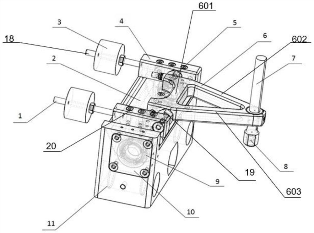
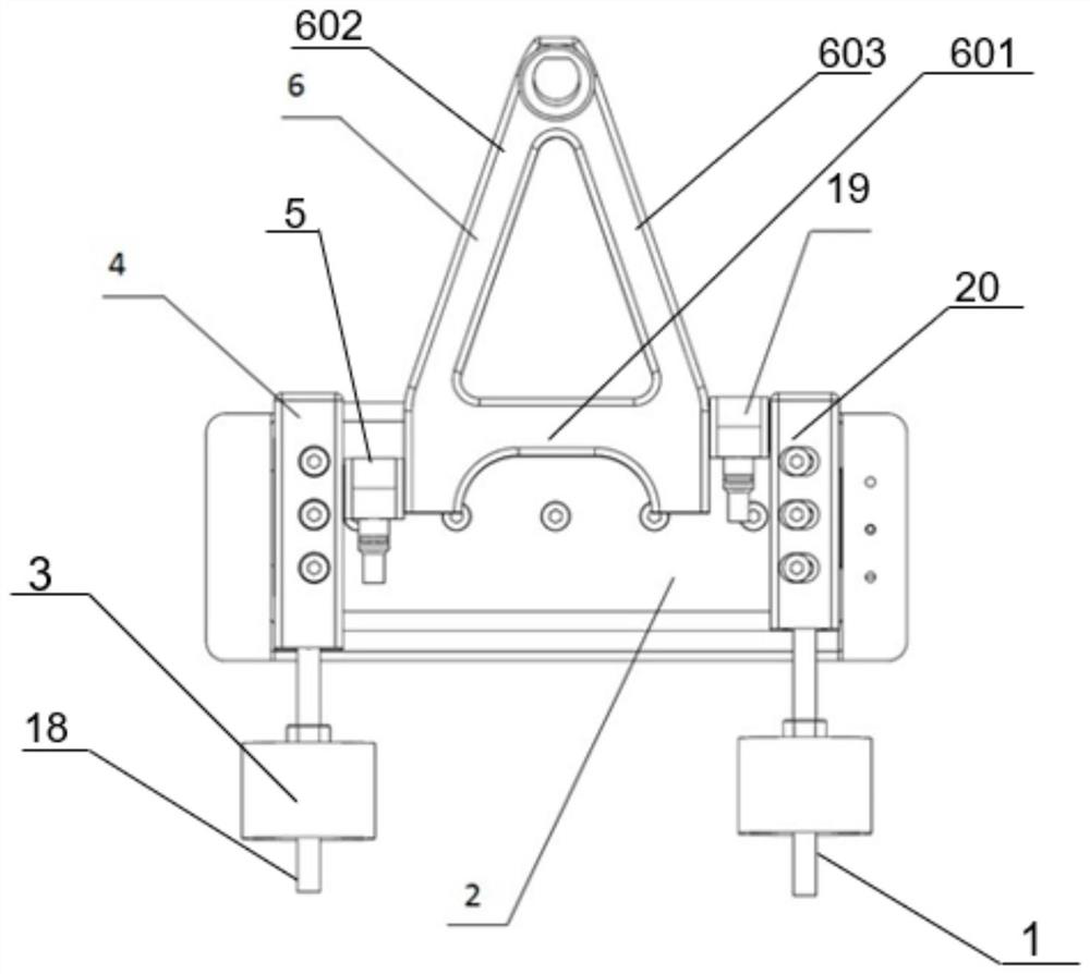
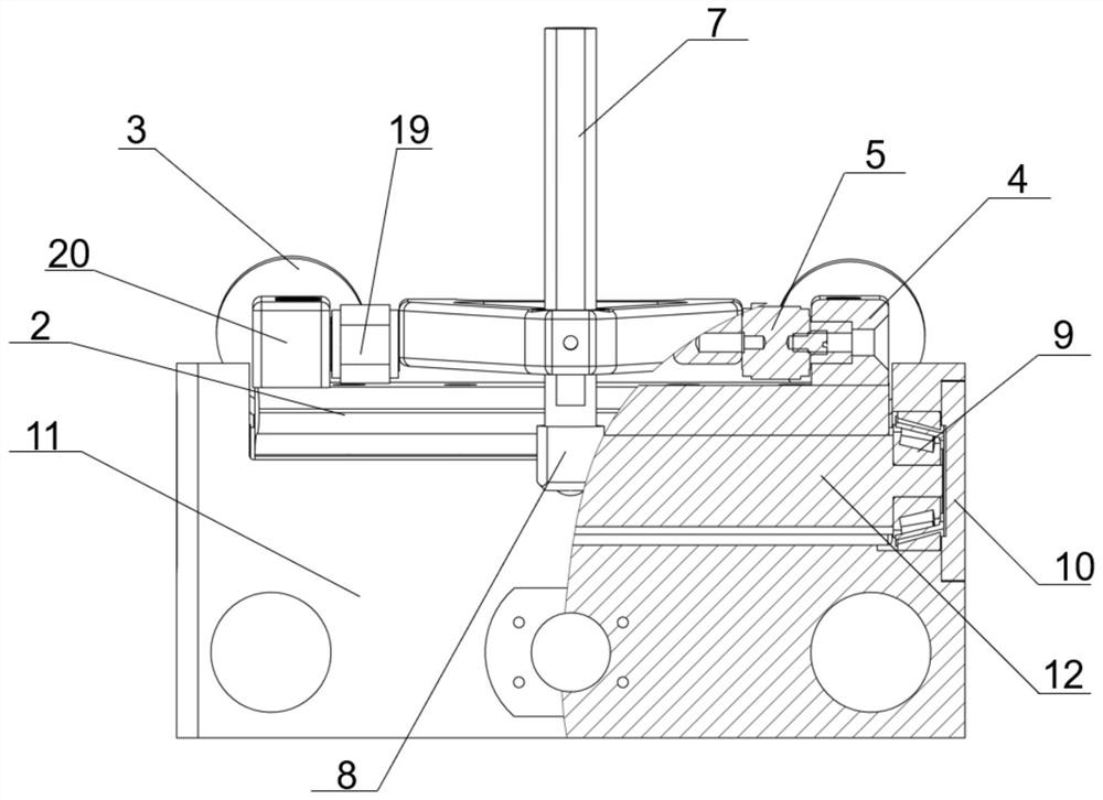
[0028] see figure 1 , in one embodiment, a friction and wear testing machine force measuring device, mainly used for fretting friction and wear, the force measuring device includes a base 11, a bearing 9, a first piezoelectric ceramic sensor 19, a second piezoelectric ceramic sensor 5. Piezoelectric ceramic sensor holder 2, first support block 20, second support block 4, first threaded rod 1, second threaded rod 18, cantilever beam 6, fixture; first piezoelectric ceramic sensor 19 and second The measuring range of piezoelectric ceramic sensor 5 is 0~45N;
[0029] Wherein, a shaft is arranged inside the base 11, and two bearings 9 are sleeved on both ends of the shaft respectively, and the bearing 9 and the shaft are in interference fit, and the piezoelectric ceramic sensor fixing seat 2 is fixedly connected to the bearing 9;
[0030] The surface of the piezoelectric ceramic sensor holder 2 is in the shape of a groove, one end of the groove is fixed to the first support block ...
Embodiment 2
[0042] This embodiment provides a friction and wear testing machine, including the force measuring device of the friction and wear testing machine in Embodiment 1.
[0043] like Figure 4 As shown, the friction and wear testing machine comprising the force measuring device in Embodiment 1 includes a fixed base 13, a driving part 15, a sample stage 14, and a distance adjustment device 16, and the base 11 of the force measuring device is provided with a hole through which The shaft on the distance adjustment device, the force measuring device can move on the shaft of the distance adjustment device, the fixture sleeve 8 contacts the sample, the sample is installed on the sample table 14, and the output shaft of the driving part is fixed on the sample table 14, which is used to drive the sample table 14 moves, so that the friction pair installed in the fixture cover 8 and the sample have relative motion, and then the pressure loaded on the sample is the weight 17 placed on the can...
PUM
 Abstract
Description
Claims
Application Information