Digital oscilloscope, method for measuring Bode plot, and readable storage medium
A technology of digital oscilloscope and wave detection, applied in digital variable display, digital variable/waveform display, measuring device, etc. It can solve the problems of limiting the dynamic range of Bode plot and poor effect of Bode plot, etc., to filter out the interference of noise signals , improve the measurement error, improve the effect of signal-to-noise ratio
- Summary
- Abstract
- Description
- Claims
- Application Information
AI Technical Summary
Problems solved by technology
Method used
Image
Examples
Embodiment 1
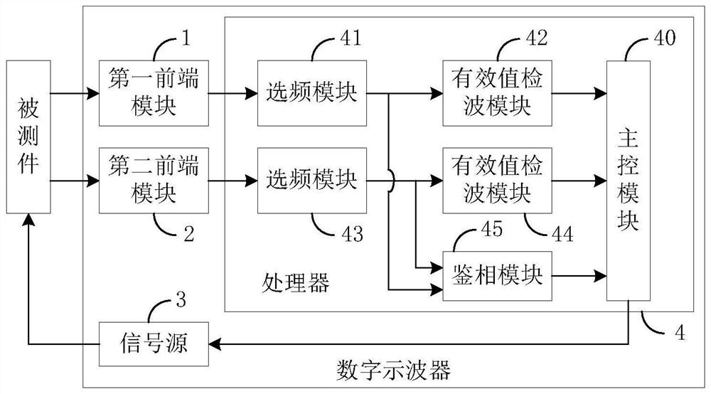
[0042] figure 2 A schematic structural diagram of a digital oscilloscope in an embodiment of the present invention is shown, as figure 2 As shown, the digital oscilloscope includes a first front-end module 1, a second front-end module 2, a signal source 3 and a processor 4, wherein the processor 4 includes: a main control module 40, a frequency selection module corresponding to the first front-end module 1 41, an effective value detection module 42, a frequency selection module 43 corresponding to the second front-end module 2, an effective value detection module 44, and a phase detection module 45. The main control module 40 is connected with the signal source 3, and is used to control the parameters of the signal source 3, such as parameters such as the frequency of the control signal source 3 and the amplitude of the output signal; The excitation signal of the test frequency, the signal source 3 inputs the excitation signal to the input port of the DUT to detect the DUT....
Embodiment 2
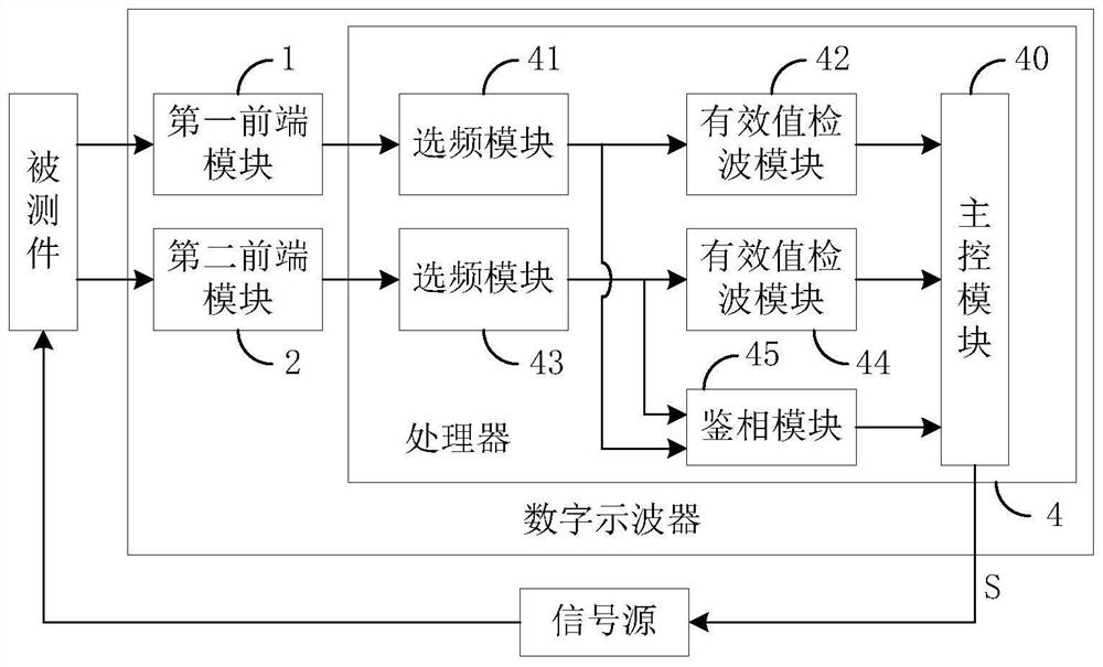
[0046] Embodiment 1 is described by taking the signal source integrated in the digital oscilloscope as an example. In practical applications, an external signal source can also provide the excitation signal. Based on this, the digital oscilloscope may only include the first front-end module, at least one first Two front-end modules and a processor, the processor includes a main control module, a phase detection module corresponding to the second front-end module, a frequency selection module and an effective value detection module corresponding to the first front-end module and the second front-end module respectively.
[0047] Similarly, taking a digital oscilloscope including a second front-end module as an example, the structural diagram of the digital oscilloscope can be found in image 3 , including a first front-end module 1, a second front-end module 2 and a processor 4, wherein the processor 4 includes: a main control module 40, a frequency selection module 41 correspon...
Embodiment 3
[0049] Based on the digital oscilloscope described in Embodiment 1, Figure 4 A schematic diagram of the structure of a specific digital oscilloscope is shown, such as Figure 4 shown, with figure 2 The difference is that the first front-end module 1 of the digital oscilloscope includes an analog front-end 11 and an analog-to-digital converter 12, the second front-end module 2 includes an analog front-end 21 and an analog-to-digital converter 22, and the frequency selection module 41 includes a signal search unit 411 and The filtering unit 412, the frequency selection module 43 include a signal search unit 431 and a filtering unit 432; the effective value detection module 42 is also used to control the gain parameter of its corresponding first front-end module 1 according to the detection result, and the first front-end module 1 is then based on this The gain parameter performs signal conditioning on the collected input signal; the effective value detection module 44 is also...
PUM
 Abstract
Description
Claims
Application Information
 - R&D
- Intellectual Property
- Life Sciences
- Materials
- Tech Scout
- Unparalleled Data Quality
- Higher Quality Content
- 60% Fewer Hallucinations
Browse by: Latest US Patents, China's latest patents, Technical Efficacy Thesaurus, Application Domain, Technology Topic, Popular Technical Reports.
© 2025 PatSnap. All rights reserved.Legal|Privacy policy|Modern Slavery Act Transparency Statement|Sitemap|About US| Contact US: help@patsnap.com


