Switched reluctance generator current conversion system with self-variable power generation voltage self-charging function

A technology of switched reluctance and current system, which is applied in the direction of controlling the generator through the change of the magnetic field, controlling the generator, and controlling the system, etc. Effects of system volume, reduced switching loss, and reduced complexity

Active Publication Date: 2019-09-06
CHINA JILIANG UNIV
View PDF4 Cites 2 Cited by
  • Summary
  • Abstract
  • Description
  • Claims
  • Application Information

AI Technical Summary

Problems solved by technology

[0003] In the operation control mode of the switched reluctance generator, the conventional angle position control, current chopper control, and the latest excitation voltage disturbance control are all unable to control the generated voltage, and according to the switched reluctance generator The mathematical model shows that the relationship between the motion electromotive force of the switched reluctance generator and the generated voltage is directly related to the trend of the winding current generation during the power generation stage, which in turn affects the power generation capacity of the switched reluctance generator. The motion electromotive force is directly related to the speed. If the power generation voltage is no longer controllable, the winding current in the power generation stage will be uncontrollable. In recent years, there have been some structures and methods to change the power generation voltage, but they all need to add additional structures and control methods to achieve it. Increased structure and control The complexity reduces the reliability. In addition, some electrical loads have the need to adjust the voltage according to the actual situation, which can only be realized by adding an additional voltage regulating device alone.
[0004] The excitation methods of switched reluctance generators generally include separate excitation and self-excitation. The excitation of the external excitation mode is stable and does not affect the output terminal, but the maintenance cost is high and requires a separate excitation power supply such as a battery. The self-excitation mode does not require a separate power supply. The separately excited type has the disadvantages of often replacing the battery, etc., but it will generally cause large fluctuations at the output end, and at the same time, the input excitation power is unstable and the power quality is low; at present, there are also some excitation methods, which are powered by the battery and absorb the advantages of the separately excited type. , when necessary, use the electric energy at the output end to charge the battery, which also absorbs the advantages of the self-excited type, but most of them need to increase the isolation link, which increases the complexity of the structure and the volume weight

Method used


Image

  • Switched reluctance generator current conversion system with self-variable power generation voltage self-charging function

Examples


Embodiment Construction

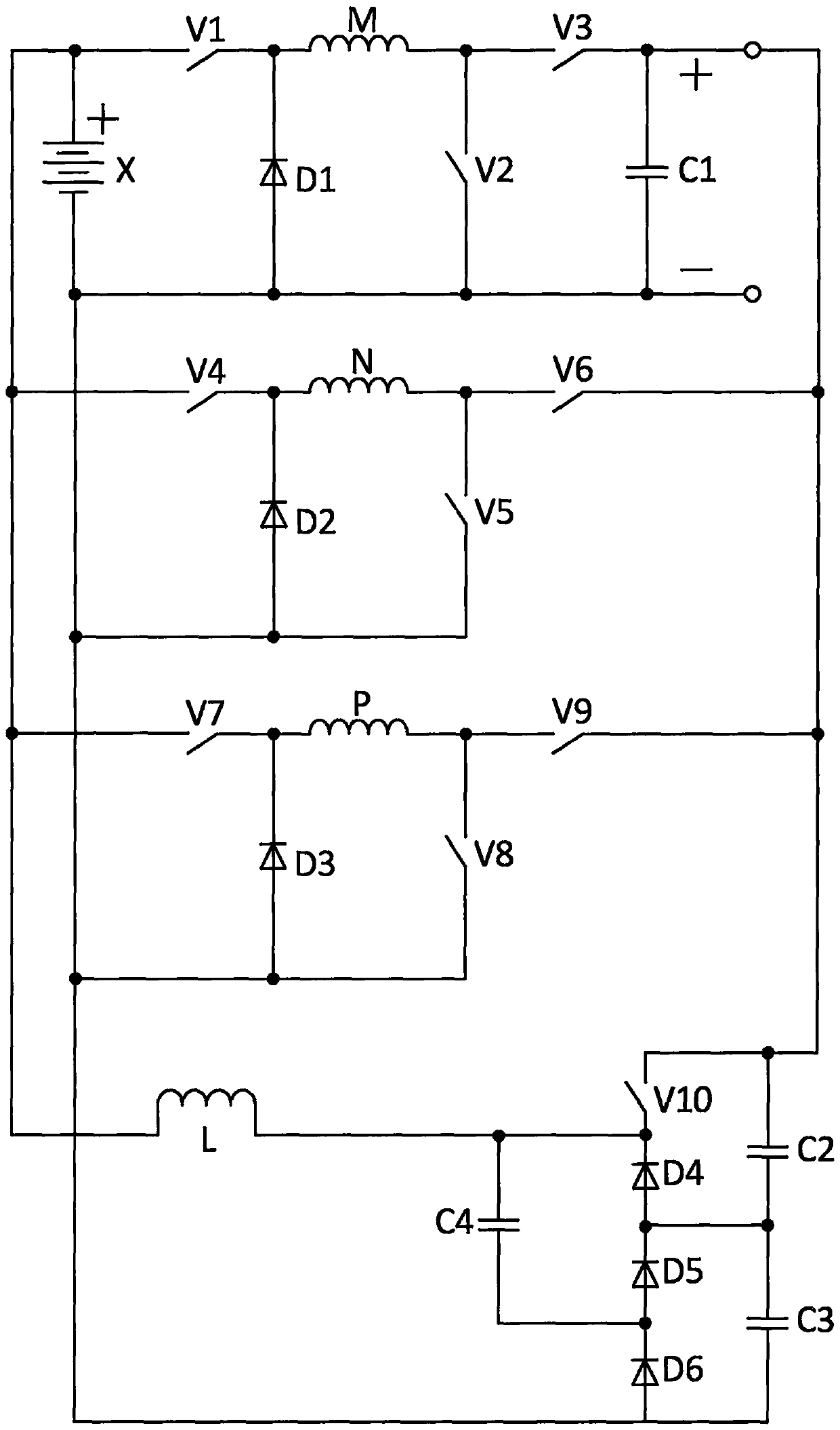
[0023] The switched reluctance generator converter system with self-variable generating voltage and self-charging in this embodiment, the converter circuit structure is as attached figure 1As shown, it consists of battery X, first switch tube V1, second switch tube V2, third switch tube V3, fourth switch tube V4, fifth switch tube V5, sixth switch tube V6, seventh switch tube V7, Eighth switch tube V8, ninth switch tube V9, tenth switch tube V10, first diode D1, second diode D2, third diode D3, fourth diode D4, fifth diode Tube D5, sixth diode D6, first phase winding M, second phase winding N, third phase winding P, first capacitor C1, second capacitor C2, third capacitor C3, fourth capacitor C4, inductor L Composition, the positive pole of the battery X is connected to the anode of the first switching tube V1, the anode of the fourth switching tube V4, the anode of the seventh switching tube V7, and one end of the inductor L, the cathode of the first switching tube V1 is conn...


PUM


Abstract

Disclosed is a switched reluctance generator current conversion system with a self-variable power generation voltage self-charging function; the switched reluctance generator current conversion systemconsists of a storage battery, ten switch tubes, six diodes, four capacitors, a three-phase winding and an inductor, and the whole current conversion system structure does not need an isolation link;the problem that the power generation voltage cannot be actively adjusted is solved by means of the current conversion system and the control method thereof, so that the adaptability of the system isgreatly improved; in the fourth and fifth modes of high-voltage output, the current can be relatively quickly reduced by changing the reverse voltage mode of the phase winding, so that the power generation current in the power generation stage is indirectly controlled, the power generation output capability is improved, the power generation output capacity is also improved and no extra device isneeded by means of the current conversion system; the storage battery can be automatically charged through the PWM effect of only one tenth switch tube; and the system is suitable for the various fields applied to the switched reluctance generators, such as the application of the wind power field.

Description

technical field [0001] The invention relates to the field of switched reluctance motor systems, in particular to a system and a control method thereof which can change the voltage generated at an output end by the switched reluctance generator converter itself, and can also automatically charge an excitation storage battery. Background technique [0002] Because of its simple and firm structure, no winding on the rotor, convenient heat dissipation, high reliability, and strong fault tolerance, the switched reluctance motor has a wide range of application prospects. [0003] In the operation control mode of the switched reluctance generator, the conventional angle position control, current chopper control, and the latest excitation voltage disturbance control are all unable to control the generated voltage, and according to the switched reluctance generator The mathematical model shows that the relationship between the motion electromotive force of the switched reluctance gen...

Claims


Application Information

Patent Timeline
Patent Type & Authority Applications(China)
IPC IPC(8): H02P9/30H02P9/38H02P101/15
CPCH02P9/305H02P9/38H02P2101/15
Inventor 孙冠群宋春伟
Owner CHINA JILIANG UNIV
Why Eureka
Try Eureka