Infusion control device

A control device and controller technology, applied in flow control, non-electric variable control, control/regulation system, etc., can solve the problems of secondary pollution of liquid medicine, complex structure, unfavorable promotion and use, etc., and achieve effective infusion control, The structure of the device is simple and the effect of infusion reminder is convenient

Active Publication Date: 2019-09-10
翁作森
View PDF7 Cites 0 Cited by
  • Summary
  • Abstract
  • Description
  • Claims
  • Application Information

AI Technical Summary

Problems solved by technology

It is unrealistic for nurses or nurses to keep an eye on the progress of the infusion. Usually, a nurse or nurse has to take care of multiple patients in multiple wards at the same time. If there is no timely reminder, it is impossible to deal with it in time.
[0005] The infusion reminding device in the prior art generally judges whether the infusion is completed by detecting the change in the weight of the infusion system during the infusion process. This kind of device needs to set the weight value in advance, which is inconvenient to use and has a large error in the alarm time; another kind of infusion reminder The device is to set up a bypass from the infusion pipeline, detect the change of the liquid medicine in the bypass, and send out a warning signal. This kind of device is easy to cause secondary pollution of the liquid medicine, and the safety is poor.
[0006] There is also a device in the prior art that uses a sensor to detect changes in the liquid medicine in the infusion tube, and sends a warning signal when the liquid medicine in the infusion tube changes from presence to absence. The advantage of this type of device is non-contact detection with the liquid medicine, There is no hidden danger of secondary pollution, and it is easy to use; but such a structure is complicated, costly, and not conducive to large-scale promotion and use
[0007] The infusion reminder devices in the prior art have certain shortcomings, such as complex structure, high cost, indirect pollution to medicine, inability to effectively control the speed of medicine infusion, etc.

Method used


Image

  • Infusion control device

Examples


Embodiment Construction

[0026] The infusion control device of the present invention can be made of, but not limited to, the following materials, for example: plastic, silica gel, aluminum alloy, titanium alloy, thermoplastic, polytetrafluoroethylene, stainless steel, and the like.

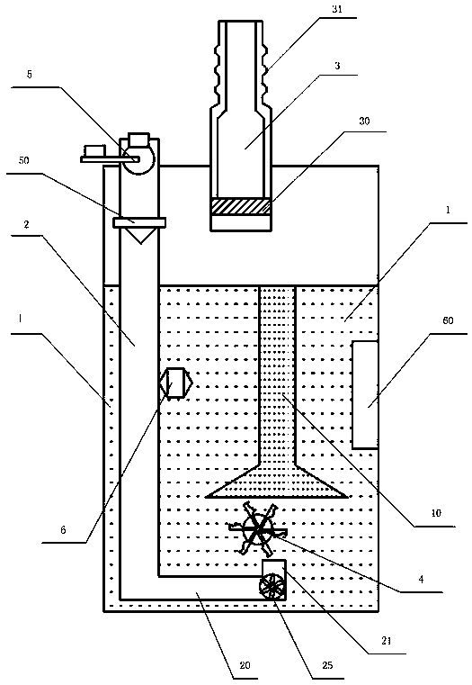
[0027] like figure 1 Shown is the side structural view of the infusion control device of the embodiment of the present invention; the infusion control device of the embodiment of the present invention is used to be connected to the air inlet conduit of the infusion bottle, that is, to be used on the air inlet of the infusion bottle, The monitoring and control of the infusion process is realized through the control and monitoring of the air intake of the infusion bottle.

[0028] This embodiment includes: a sealed cavity 1, an electric control valve 5, a photoelectric counter 6 and an air intake pipe 2; the cavity 1 is generally a transparent plexiglass cavity.

[0029] The cavity 1 is sealed with liquid, and the liquid i...


PUM


Abstract

The invention provides an infusion control device, and belongs to the field of medical device manufacturing. The infusion control device comprises a closed container, an electrical control valve, a photoelectric counter and an air inlet pipe, wherein the container is hermetically filled with liquid; the air inlet pipe is provided with an air inlet and an air outlet, and the air inlet pipe is inserted into the container; the air inlet is formed in the outer side on the top of the container, and the air outlet is below the liquid surface of the liquid; an air outlet pipe is further arranged on the top of the container; the electrical control valve is installed on the air inlet pipe. A rotating wheel capable of rotation in the vertical plane is further installed in the container; the rotatingwheel is below the liquid surface and above the air outlet; the photoelectric counter is above the air outlet. By installing the infusion control device on an air inlet guide pipe, counting is conducted through bubbles in the liquid in the closed space, it is thus achieved that the infusion speed and flow are effectively detected and controlled, infusion prompting can be achieved, and moreover, infusion can be effectively controlled.

Description

technical field [0001] The invention relates to a medical device manufacturing technology, in particular to an infusion control device, which belongs to the technical field of common medical product manufacturing. Background technique [0002] Infusion is a common medical method. When patients are infusion, they usually need the care of medical staff or family members. [0003] During the infusion process, patients or their family members must always pay attention to the progress of the infusion. If the treatment is not timely, when the liquid level drops below the drip pot, air may enter the blood. When the air entering the human body reaches a certain amount, there will be Air embolism may result, causing distress to the patient. Blood may also flow back down the dropper, causing panic for the patient. [0004] Because the infusion time is long, usually more than half an hour, the patient or family members are required to keep an eye on the progress of the infusion, wh...

Claims


Application Information

Patent Timeline
Patent Type & Authority Applications(China)
IPC IPC(8): A61M5/168A61M5/172
CPCA61M5/16813A61M5/16831A61M5/16881
Inventor 翁作森杨云云常明香
Owner 翁作森
Why Eureka
Try Eureka