Air control delay device for fire extinguishing control system

A technology of a control system and a delay device, applied in fire rescue and other directions, can solve the problems of inappropriate restoration of the original state, disorder of the delay control program, affecting the delay action, etc., so as to reduce the impact of manufacturing, installation and operation accuracy, Reduce casualties and property losses, and achieve the effect of time delay

Pending Publication Date: 2019-09-10
CHINA NON-FERROUS METALS PROCESSING TECH CO LTD
View PDF0 Cites 1 Cited by
  • Summary
  • Abstract
  • Description
  • Claims
  • Application Information

AI Technical Summary

Problems solved by technology

The first type of electrical delay control system will be affected by unfavorable factors such as internal electronic circuit failures, external lightning strikes, and electromagnetic interference during operation, which may cause disorder in the delay control program and cause malfunctions
The misoperation of this kind of electrical delay control makes the fire extinguishing signal fail to complete the evacuation delay and send out the fire extinguishing signal, which causes the fire extinguishing system to spray carbon dioxide gas in advance, causing casualties
The second type of mechanical spring-type delay timer, which uses many non-standard machining parts, is affected by processing installation and operation accuracy, the timer may be stuck during the delay process, and the delay function will be lost; After the delay ends, the recovery process is more complicated. Non-professional security personnel cannot quickly restore the original state or the restored original state is inappropriate, which will affect the next delay action
The time delay of this kind of mechanical delay control does not send out the fire extinguishing signal in time, which causes the fire extinguishing system to delay the discharge of carbon dioxide gas, and cannot extinguish the fire in time, causing property losses.

Method used


Image

  • Air control delay device for fire extinguishing control system
  • Air control delay device for fire extinguishing control system

Examples


Embodiment Construction

[0020] The present invention can be explained in detail through the following examples, and the purpose of disclosing the present invention is to protect all technical improvements within the scope of the present invention.

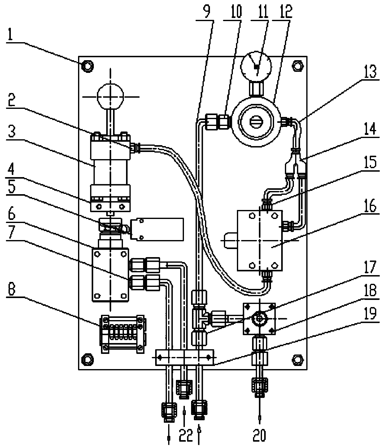
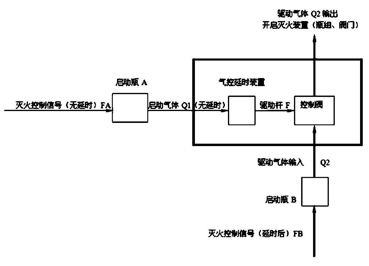
[0021] combined with Figure 1-2 The air-controlled delay device for the fire extinguishing control system includes an installation base plate 1, an action cylinder 3 fixed on one side of the installation base plate 1, and a two-position two-way straight-through valve 6, which are fixed on the other side of the installation base plate 1 Pressure reducing valve 12, air-controlled timer 16, two-position two-way manual reversing valve 18, two-position two-way straight-through valve 6 is arranged directly above the action cylinder 3, and the piston rod of the action cylinder 3 is directly connected to the two-position two-way The axis of the valve 6 coincides, and there is a distance gap between the action end of the two-position two-way straight-through valv...


PUM


Abstract

The invention discloses an air control delay device for a fire extinguishing control system, and relates to the technical field of fire protection fire extinguishing. A two-position two-way straight-through valve is arranged over an action air cylinder, and a pressure reduction valve, an air control timer and a two-position two-way manual reversing valve are arranged from top to bottom at intervals, and an air inlet and an air outlet of the two-position two-way straight-through valve communicate with a second air inlet and a second air outlet through pipelines correspondingly. The pressure reduction valve communicates with a first air inlet through a copper pipe. The copper pipe is provided with a three-way cutting ferrule connector B. One branch pipe of the three-way cutting ferrule connector B is connected with an air inlet of the two-position two-way manual reversing valve, an air outlet of the two-way manual reversing valve is connected with a first air outlet, the pressure reduction valve is connected with one branch head in a three-way cutting ferrule connector A through a hose, and the other two branch connectors of the three-way cutting ferrule connector A are connected with an air inlet and a signal air inlet of the air control timer through pipelines correspondingly. By means of the air control delay device, the purpose of fire disaster detecting and fire extinguishing agent releasing time delay is achieved.

Description

technical field [0001] The invention relates to the technical field of fire extinguishing, in particular to an air-controlled delay device used in a fire extinguishing control system. Background technique [0002] It is known that the main component of process lubricants used in non-ferrous metal strip cold rolling mills is kerosene-based, which can easily be ignited during the production process due to rolling deformation of rolled materials, overheating of mechanical equipment, static electricity accumulation, broken strips, etc. Lubricants cause fires. In order to avoid the expansion of losses, it is necessary to spray carbon dioxide gas fire extinguishing agent in time to extinguish the fire. However, after the carbon dioxide reaches a certain concentration and the low temperature effect generated during the spraying process is dangerous to personal safety. When the carbon dioxide content in the air reaches 15%, short-term inhalation can cause the personnel to lose consc...

Claims


Application Information

Patent Timeline
Patent Type & Authority Applications(China)
IPC IPC(8): A62C37/40
CPCA62C37/40
Inventor 吴存福李垒石磊刘周同杨义普高朝阳赵振涛李旭亮白峰宫晓波王光林梁彦峰
Owner CHINA NON-FERROUS METALS PROCESSING TECH CO LTD
Why Eureka
Try Eureka