

Cement loading barrel and matched stirring barrel thereof
A mixing tank and cement technology, which is applied in the cement field, can solve the problems of cement being susceptible to moisture, large cement dust, etc., and achieve the effect of convenient feeding
- Summary
- Abstract
- Description
- Claims
- Application Information
AI Technical Summary
Problems solved by technology
Method used
Image

Examples
Embodiment Construction
[0028] Hereinafter, embodiments of the present invention will be described in detail, examples of which are shown in the accompanying drawings and the following description. While the invention will be described in conjunction with exemplary embodiments, it will be understood that the description is not intended to limit the invention to the exemplary embodiments. On the contrary, the invention is to cover not only the exemplary embodiment, but also various alternatives, modifications, equivalents and other embodiments, which may be included within the spirit and scope of the invention as defined by the appended claims Inside.
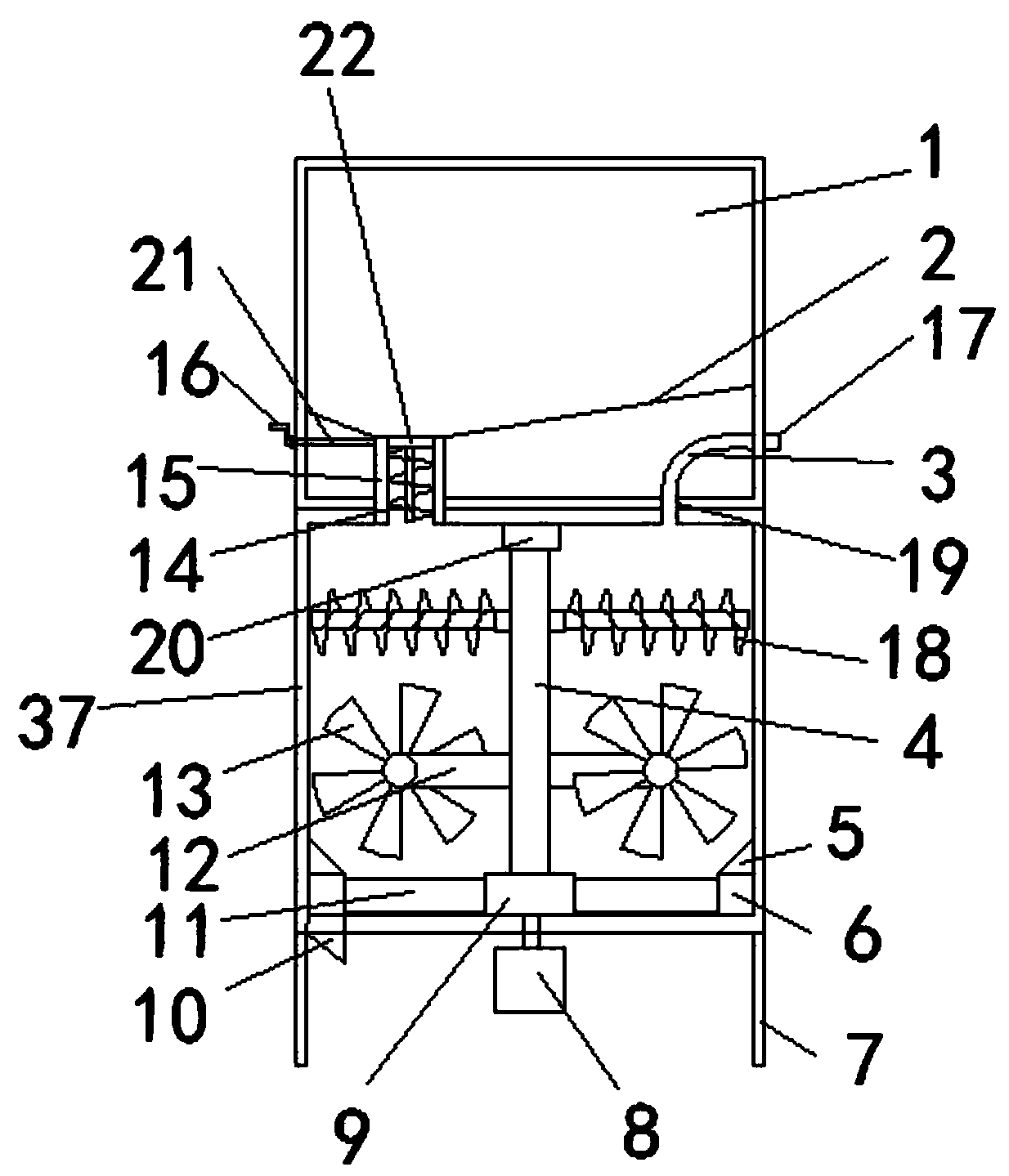
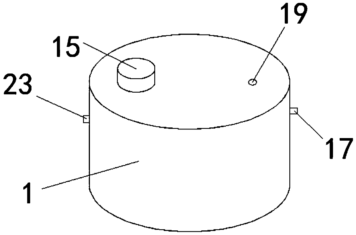
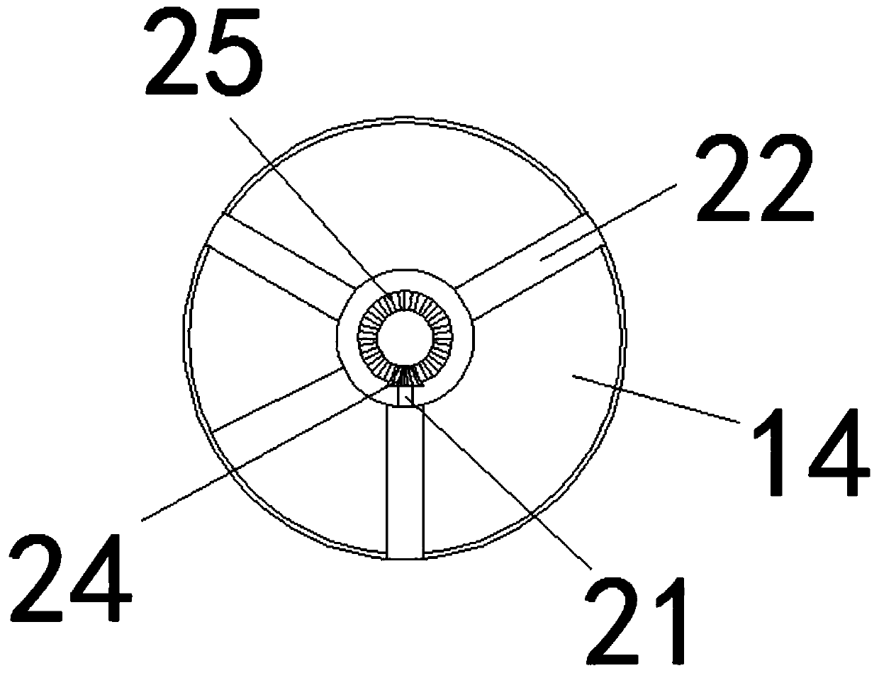
[0029] see figure 1 to attach Figure 8 , a cement loading bucket and its matching mixing bucket, comprising a cement bucket 1, a compartment 2, a water pipe 3, a sleeve shaft 4, an inclined ring 5, a discharge ring 6, a support rod 7, a motor 8, a fixed plate 9, Discharge port 10, rotating blade 11, fixed rod 12, stirring blade 13, cement bucket ro...
PUM
 Abstract
Description
Claims
Application Information