Condensing type afterheat recovering and water heating cooking oven

A waste heat recovery and condensing technology, which is applied in the field of boiler waste heat recovery, can solve the problems of low utilization rate of gas heat energy, low heat utilization efficiency, waste of gas heat energy, etc., and achieve the goal of reducing heat pollution, improving utilization rate, and thorough heat exchange Effect

Pending Publication Date: 2019-09-10
南充烽英堂厨房电器设备科技有限公司
View PDF0 Cites 0 Cited by
  • Summary
  • Abstract
  • Description
  • Claims
  • Application Information

AI Technical Summary

Problems solved by technology

From the thermal efficiency of gas stoves, it can be seen that the utilization rate of gas heat energy in household gas stoves is generally not high, and about 40-50% of gas heat energy is wasted in use.
The combustion method of the commercial gas stoves currently used in the market still adopts the traditional positive pressure open combustion method. During the gas combustion process, the combustion flame and high-temperature flue gas are directly leaked out, resulting in the formation of a large number of high-temperature incomplete combustion after the gas is burned. Carbon gas is directly discharged into the surrounding environment, so that only a small part of the heat generated by gas combustion is used by the pot, and the heat utilization efficiency is extremely low
Moreover, due to the release of incompletely burned gas and the surrounding environment, air pollution and noise pollution will be brought
Therefore, whether it is a domestic gas cooker or a commercial gas cooker, it is facing a serious problem of energy waste during use.

Method used


Image

  • Condensing type afterheat recovering and water heating cooking oven
  • Condensing type afterheat recovering and water heating cooking oven
  • Condensing type afterheat recovering and water heating cooking oven

Examples


Embodiment 1

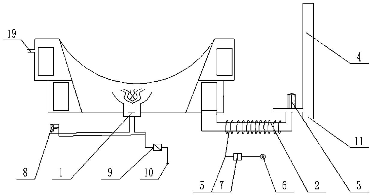
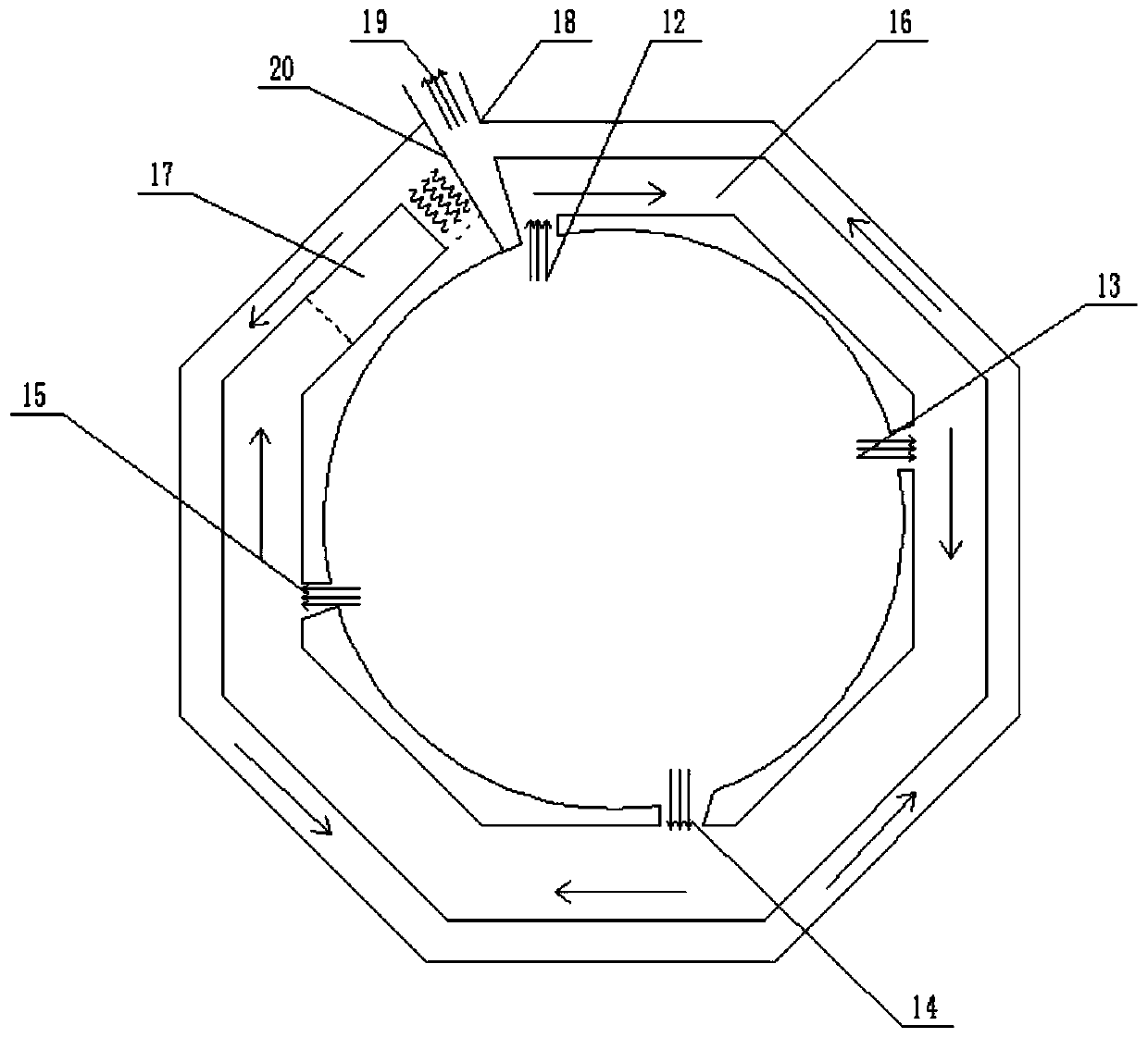
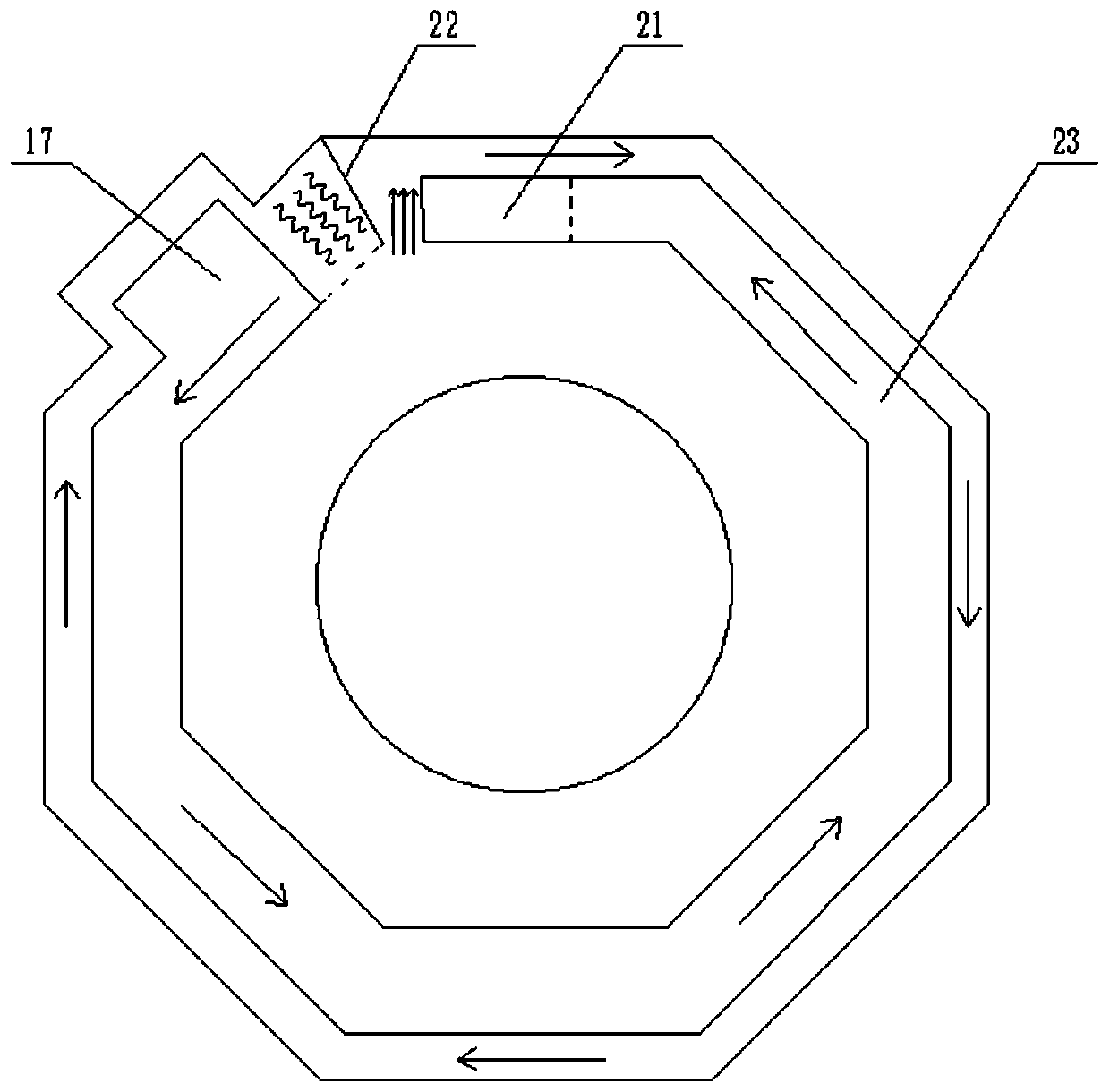
[0039] The condensing waste heat recovery hot water large pot stove provided by the preferred embodiment of the present invention includes a first air inlet 12, a second air inlet 13, a third air inlet 14 and a fourth air inlet 15; The bottom of the head 1 is connected in parallel with the gas inlet 10 and the blower 8, and the electric valve 9 is set on the connection channel between the gas inlet 10 and the burner 1; the first-stage waste heat exchange pipe 16, the second-stage waste heat exchange pipe 23, and the smoke exhaust pipe 4 It is made of stainless steel, and the fins 2 are made of copper.

[0040] When working: click the switch, the blower 8 and the strong exhaust fan 3 start to work, the ignition pulse is automatically ignited, the electric valve 9 is opened, and the fuel starts to burn; , the second air inlet 13, the third air inlet 14, and the fourth air inlet 15 are evenly sucked into the first-stage waste heat exchange pipe 16; the high-temperature exhaust ga...

Embodiment 2

[0043] In this embodiment, on the basis of the first embodiment, a solenoid valve 7 is provided on the water inlet pipe 5, and the solenoid valve 7 is located between the tap water inlet 6 and the water inlet of the water tank. It also includes a temperature probe 18 arranged inside the upper chamber.

[0044] When working: a self-operated temperature control valve integrating a temperature probe and a solenoid valve 7 is adopted. When the temperature of the upper chamber reaches the set value, the solenoid valve 7 is opened; tap water enters the water tank, the lower chamber and the upper chamber in turn; the upper chamber The high-temperature water in the chamber is discharged out of the kitchen range by the tap water outlet 19.

Embodiment 3

[0046] In this embodiment, on the basis of the first embodiment, a solenoid valve 7 is provided on the water inlet pipe 5, and the solenoid valve 7 is located between the tap water inlet 6 and the water inlet of the water tank. It also includes a temperature probe 18 arranged inside the upper chamber.

[0047] When working: the temperature probe is used to transmit the temperature information to the controller, and the controller controls the solenoid valve 7 according to the temperature information. When the temperature of the upper chamber reaches the set value, the solenoid valve 7 is opened; tap water enters the water tank, the lower chamber and the upper chamber in sequence chamber; the high-temperature water in the upper chamber is discharged out of the stove body by the tap water outlet 19; and when the solenoid valve 7 breaks down, or when the tap water is cut off; when the water temperature in the upper chamber reaches the set dangerous value; the controller controls t...


PUM


Abstract

The invention discloses a condensing type afterheat recovering and water heating cooking oven. The condensing type afterheat recovering and water heating cooking oven comprises an oven body, and a hearth which is arranged in the center of the oven body, wherein an oven head is mounted in the center of the inner middle part of the hearth; the oven body is an inverted hollow octagonal platform, andan empty chamber is formed in a circle around the outer wall of the hearth in the oven body; a horizontal separating plate is arranged in the empty chamber and divides an interlayer of the hearth intoan upper annular chamber and a lower annular chamber; a first-grade afterheat exchanging tube is arranged in the upper chamber, and a second-grade afterheat exchanging tube is arranged in the lower chamber; a plurality of high-temperature exhaust gas inlets which communicate with the inside of the hearth are formed at uniform intervals in the first-grade afterheat exchanging tube; the tail end ofthe first-grade afterheat exchanging tube is in communication connection with the head end of the second-grade afterheat exchanging tube through a first guide tube which is vertically arranged; and the tail end of the second-grade afterheat exchanging tube is connected to the head end of a smoke exhausting tube through a second guide tube. The condensing type afterheat recovering and water heating cooking oven further comprises a water tank which is connected to the smoke exhausting tube; fins are arranged around a door of a part where the water tank is connected to the smoke exhausting tube;and a water inlet of the water tank is connected to a tap water inlet through a water inlet tube.

Description

technical field [0001] The invention belongs to the field of boiler waste heat recovery, and relates to a condensing waste heat recovery hot water large boiler stove. Background technique [0002] According to statistics, the existing gas stoves in the catering industry have serious heat loss and empty burning phenomenon is common. The average thermal efficiency is only 20%, and the heat loss is as high as 80%, resulting in great energy waste. The so-called thermal efficiency of the gas stove, in layman's terms, is the effective utilization rate of the gas heat energy during the use of the gas stove. As can be seen from the thermal efficiency of gas cookers, household gas cookers generally have a low utilization rate of gas heat energy, and about 40% to 50% of gas heat energy is wasted in use. The combustion method of the commercial gas stoves currently used in the market still adopts the traditional positive pressure open combustion method. During the gas combustion proces...

Claims


Application Information

Patent Timeline
Patent Type & Authority Applications(China)
IPC IPC(8): F24C13/00F24C3/12F24C15/34
CPCF24C3/126F24C13/00F24C15/34
Inventor 任毓王尚兵
Owner 南充烽英堂厨房电器设备科技有限公司
Why Eureka
Try Eureka