Storage battery internal resistance measuring circuit and measuring method

A technology for measuring circuits and batteries, applied in the direction of measuring electrical variables, measuring electricity, measuring resistance/reactance/impedance, etc., can solve problems such as poor repeatability, interference of relay protection equipment, and difficulty, and improve measurement resolution and accuracy. degree, the hardware circuit structure is simple, and the AC discharge current is small.

Inactive Publication Date: 2019-09-13
哈尔滨佳云科技有限公司
View PDF7 Cites 4 Cited by
  • Summary
  • Abstract
  • Description
  • Claims
  • Application Information

AI Technical Summary

Problems solved by technology

[0025] The purpose of the present invention is to solve the problems that the current battery internal resistance measurement method interferes with the relay protection equipment and cause safety accidents; the measurement accuracy is low, the repeatability is poor, and the difficulty is large, which affects the monitoring effect of the internal resistance of the battery. The battery internal resistance measurement circuit and measurement method based on the discharge principle can greatly improve the accuracy and repeatability of the measurement results, and at the same time reduce the cost of the measurement device, so that it has a high performance-price ratio and market competitiveness.

Method used


Image

  • Storage battery internal resistance measuring circuit and measuring method
  • Storage battery internal resistance measuring circuit and measuring method
  • Storage battery internal resistance measuring circuit and measuring method

Examples


Embodiment 1

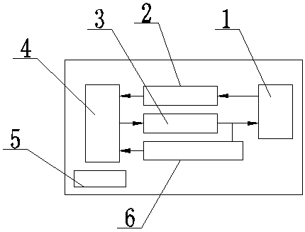
[0072] A storage battery internal resistance measurement circuit, which consists of: an MCU circuit 4 and a battery under test 1, and a voltage acquisition circuit 2, a current acquisition circuit 6 and an intelligent load circuit are connected between the MCU circuit and the battery under test 3. The smart load circuit is electrically connected to the current acquisition circuit;

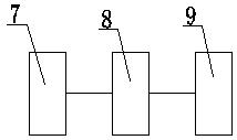
[0073] Described voltage acquisition circuit comprises digital / analog converter 7, instrumentation amplifier 8 and bandpass filter 9, and described digital / analog converter is electrically connected with described instrumentation amplifier, and described instrumentation amplifier is connected with described instrumentation amplifier The bandpass filter is electrically connected;

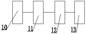
[0074] Described intelligent load circuit comprises serial interface 10, analog / digital converter 11, output converter 12 and sampling resistor 13, described serial interface, described analog / digital converter, described...

Embodiment 2

[0080] According to the storage battery internal resistance measurement circuit described in Embodiment 1, the MCU circuit adopts STM32F303CBT6 as the main control chip.

Embodiment 3

[0082] According to the battery internal resistance measuring circuit described in embodiment 1 or 2, the battery to be tested is a 2V or 12V battery.


PUM


Abstract

The invention discloses a storage battery internal resistance measuring circuit and a measuring method. In a current storage battery internal resistance measuring method, interference is generated forrelay protection equipment, and a measuring device is high in cost and low in precision. The measuring circuit comprises an MCU circuit (4) and a measured storage battery (1), wherein a voltage collection circuit (2), a current collection circuit (6) and an intelligent load circuit (3) are connected between the MCU circuit and the measured storage battery; the intelligent load circuit is electrically connected with the current collection circuit; the voltage collection circuit comprises a digital/analog converter (7), an instrument amplifier (8) and a band-pass filter (9); the digital/analogconverter is electrically connected with the instrument amplifier; the instrument amplifier is electrically connected with the band-pass filter; the intelligent load circuit comprises a serial interface (10), an analog/digital converter (11), an output converter (12) and a sampling resistor (13); and the serial interface, the analog/digital converter, the output converter and the sampling resistorare electrically connected in sequence. The measuring circuit is applied to measurement of storage battery internal resistance.

Description

[0001] Technical field: [0002] The invention relates to a method for measuring the internal resistance of a battery, in particular to a circuit and a method for measuring the internal resistance of a battery. [0003] Background technique: [0004] The battery pack is a backup DC power supply independent of the transformed AC power supply, and is the last line of defense in the power system. When the AC power supply in the computer room is interrupted, it will play the role of "independent power supply" to ensure the safe and reliable operation of the control and communication equipment in the computer room. The "maintenance-free" use of valve-regulated lead-acid batteries will cause users to relax the daily maintenance and management of batteries, and the substandard working environment will shorten the service life of batteries. Therefore, using effective monitoring methods to grasp the "health" status of the battery in real time and accurately can avoid potential safety h...

Claims


Application Information

Patent Timeline
Patent Type & Authority Applications(China)
IPC IPC(8): G01R31/389G01R27/02
CPCG01R31/389G01R27/02
Inventor 刘津义丁一许新竹
Owner 哈尔滨佳云科技有限公司
Why Eureka
Try Eureka