Complex impedance matching circularly polarized wave-filtering antenna

A filter antenna and complex impedance technology, applied in the field of filter antennas, can solve the problems of introducing filters, increased loss of impedance matching network, complex structure, etc., to achieve the effect of improving integration and reducing loss

Active Publication Date: 2019-09-13
XIAN INSTITUE OF SPACE RADIO TECH
View PDF7 Cites 6 Cited by
  • Summary
  • Abstract
  • Description
  • Claims
  • Application Information

AI Technical Summary

Problems solved by technology

[0004] The technical problem solved by the present invention is: aiming at the deficiencies of the prior art, a complex impedance matching circular polarization filter antenna is proposed, which utilizes the characteristics of each resonator in the filter antenna to realize broadband operation and harmonic suppression, and then adjusts each resonance The quality factor and coupling coefficient of the filter are used to achieve complex impedance matching, which solves the problems of increased loss and complex structure caused by the introduction of filters and impedance matching networks in traditional conventional designs.

Method used


Image

  • Complex impedance matching circularly polarized wave-filtering antenna
  • Complex impedance matching circularly polarized wave-filtering antenna
  • Complex impedance matching circularly polarized wave-filtering antenna

Examples


Embodiment

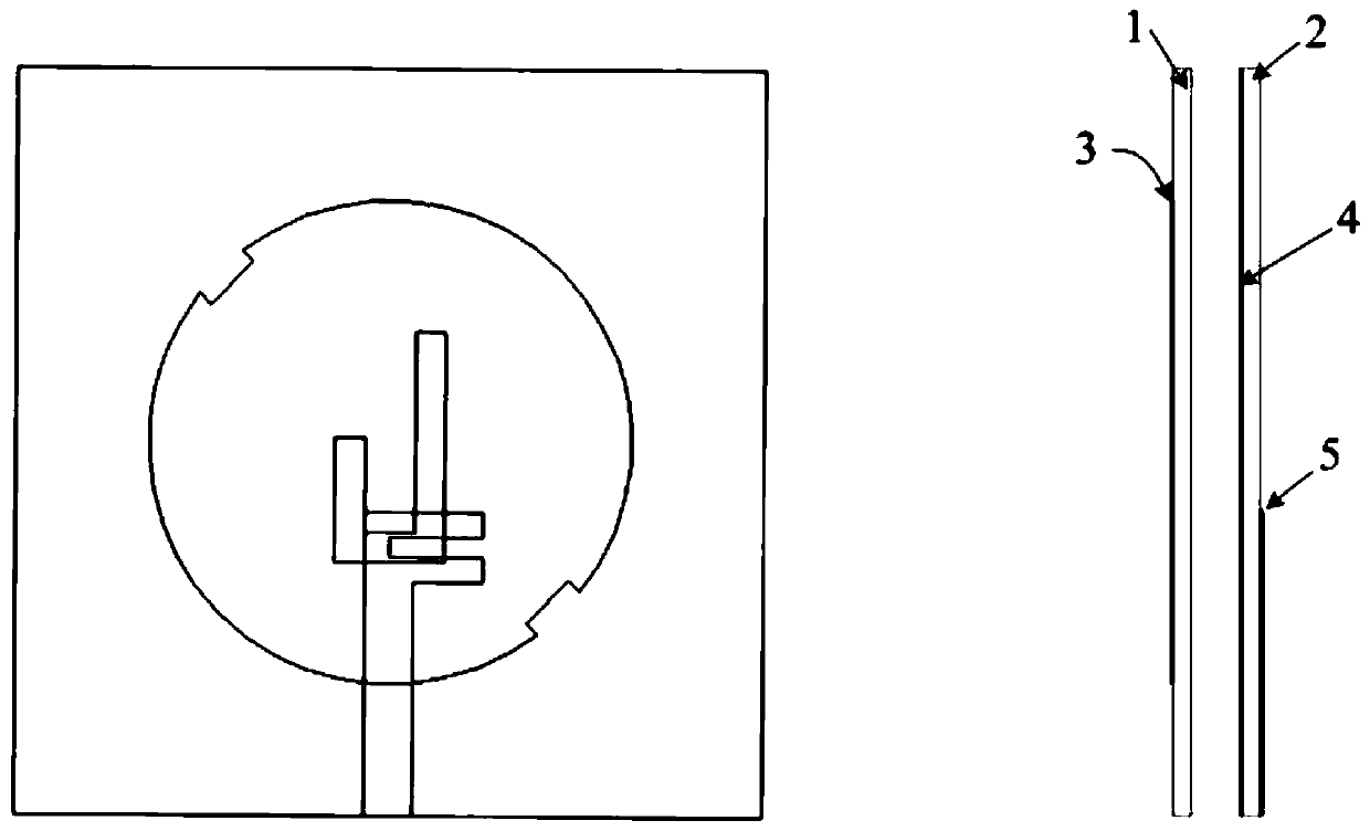
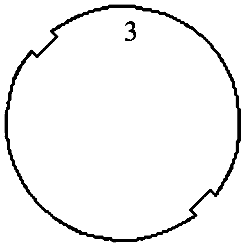
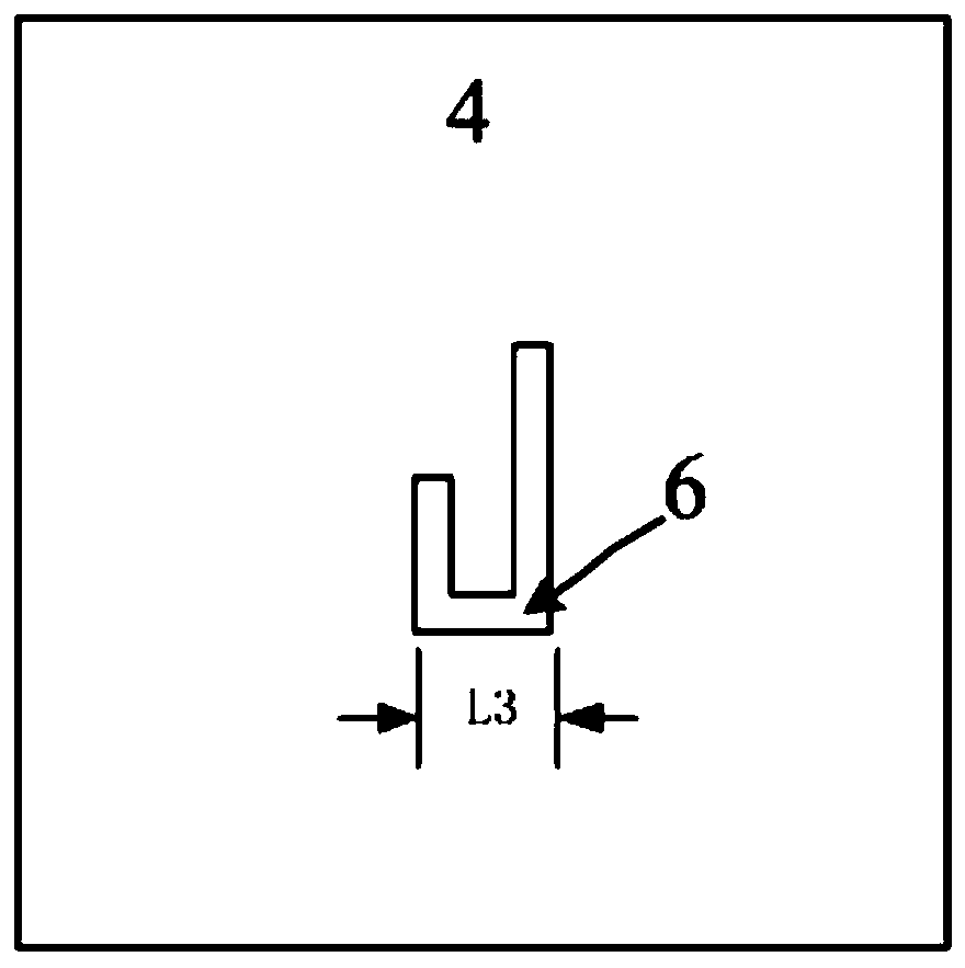
[0031] A simulation study is carried out on an example of a complex impedance matching circularly polarized filter antenna with a working frequency of 5.8GHz. The antenna works at 5.8GHz and is printed on two layers of Rogers 4003C substrates (ε r =3.55, tanδ=0.009), the thickness is 0.813mm. The distance between the two substrates is 2mm. Radiation elements are etched on the top layer of the upper substrate. It is a circular patch with a notch. Asymmetrical U-shaped slots are etched on the middle floor for circularly polarized radiation. In the feeding structure, a U-shaped microstrip line resonator and a radiation patch are used to form a filtering function.

[0032] A typical input impedance of a specific rectification circuit obtained in the rectification circuit simulation study is 73.5+j106.3Ω as the complex impedance matching target. The input impedance of the filter antenna should be matched to its conjugate for maximum power transfer. A filter antenna with an in...


PUM


Abstract

The present invention discloses a complex impedance matching circularly polarized wave-filtering antenna. The antenna comprises two dielectric substrates and three metal layers. Air is filled betweenthe two substrates. An antenna radiation unit is located on the top layer of a first dielectric substrate, and the antenna radiation unit is a circular metal patch with notches. A grounding metal layer is located on the upper layer of the second substrate, and the grounding metal layer is etched with an asymmetrical U-shaped groove. A wave-filtering feed structure is located on the bottom layer ofthe second substrate, and the terminal of a micro-strip line is connected with a hairpin-shaped micro-strip resonator. By adjusting the U-shaped micro-strip line resonator and the size of a couplinggap, and tuning quality factor(s) and a coupling coefficient(s) in a coupling matrix, the complex impedance matching of the antenna is realized; by performing resonant tuning via the U-shaped micro-strip line resonator and the circular patch, the working bandwidth of the antenna is expanded, and meanwhile the second harmonic suppression is realized. According to the antenna, the antenna wide-bandworking is realized, and meanwhile the second harmonic suppression and the complex impedance matching can be ensured.

Description

technical field [0001] The invention belongs to the technical field of antennas and microwaves, and relates to a filtering antenna. Background technique [0002] In the existing wireless radio frequency system, various circuits such as the antenna and filter of the radio frequency front-end are mostly independently designed, and then connected together through radio frequency connectors and cable levels, there are problems such as impedance matching and additional insertion loss. In the filter antenna design, the antenna becomes a component of the filter circuit, and it is necessary to design, simulate and optimize the antenna and filter circuit at the same time. [0003] Compared with traditional antennas, filter antennas do not require a separate impedance matching network between the antenna and the RF circuit, and also have advantages such as compact size, low loss, wide bandwidth, high-frequency selectivity, broadband harmonic suppression, improved out-of-band rejection...

Claims


Application Information

Patent Timeline
Patent Type & Authority Applications(China)
IPC IPC(8): H01Q1/38H01Q1/48H01Q1/50H01P7/08
CPCH01P7/082H01Q1/38H01Q1/48H01Q1/50
Inventor 董亚洲董士伟禹旭敏王颖刘硕李小军朱舸
Owner XIAN INSTITUE OF SPACE RADIO TECH
Why Eureka
Try Eureka