
Radio frequency/laser cooperative rapid capturing, tracking and aligning method

A laser tracking and radio frequency technology, used in electromagnetic wave transmission systems, electrical components, transmission systems, etc., can solve the problems of limited transmission distance of beams with large divergence angles, inability to achieve rapid beam capture, and difficulty in automatic adjustment of the field of view. Fast capture and precise tracking alignment, reduced capture alignment time, short scan time effect

Active Publication Date: 2019-09-13
10TH RES INST OF CETC
View PDF6 Cites 12 Cited by
  • Summary
  • Abstract
  • Description
  • Claims
  • Application Information

AI Technical Summary

Problems solved by technology

The main disadvantages of this method are: first, the transmission distance of the light beam with a large divergence angle is limited, and it can only be captured in a short distance, and cannot be used for a long-distance mobile platform; second, the optical detector with a large field of view needs to capture the light beam Using image tracking, in the case of complex background, it is difficult to extract the image target and automatically adjust the size of the field of view, and it needs to be assisted by a certain amount of manual operation, and it is impossible to realize the automatic fast capture of the beam; the third is on the platform with high mobility and strong vibration In the application environment, the narrow beam signal is very easy to lose. Once the optical signal is lost by the existing optical detector, it is difficult to quickly recapture the laser link in a small area.

Method used


Image

  • Radio frequency/laser cooperative rapid capturing, tracking and aligning method
  • Radio frequency/laser cooperative rapid capturing, tracking and aligning method
  • Radio frequency/laser cooperative rapid capturing, tracking and aligning method

Examples


Embodiment Construction

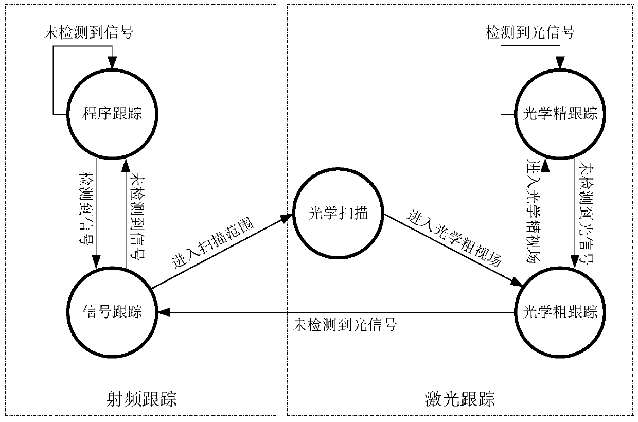
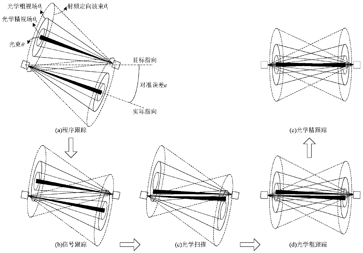
[0017] refer to figure 1 . According to the present invention, in the radio frequency / laser cooperative fast capture tracking alignment system, the capture tracking alignment is divided into radio frequency tracking and laser tracking; Information, extract the alignment error between the target pointing and the current actual pointing as the feedback amount, control the radio frequency directional beam and laser beam pointing, quickly find and capture the laser beam through the radio frequency beam assistance in the whole airspace, and then switch to laser tracking; In the laser tracking stage, the beam pointing controller uses the beam information detected by the optical coarse field of view and the fine field of view to extract the alignment error between the target pointing and the current actual pointing as a feedback value, controls the pointing of the laser beam, and aligns the laser beam in radio frequency tracking. The beam alignment error is further reduced within th...


PUM


Abstract

The invention discloses a radio frequency / laser cooperative rapid capturing, tracking and aligning method, and aims to provide a capturing, tracking and aligning method capable of rapidly capturing and aligning light beams in a high probability in a long-distance whole airspace. The invention is realized through the following technical method: in the radio frequency tracking stage, a beam pointingcontroller extracting an alignment error between a target pointing direction and a current actual pointing direction as a feedback quantity according to radio frequency omnidirectional beam and radiofrequency directional beam detection information, quickly searching for and capturing a laser beam through radio frequency beam assistance in a full airspace range, and switching to laser tracking; in a laser tracking phase, the beam pointing controller extracting an alignment error between a target pointing direction and a current actual pointing direction as a feedback quantity by respectivelyutilizing beam information detected by an optical coarse field of view and a fine field of view, controlling the laser beam pointing direction, further reducing the beam alignment error in a radio frequency tracking alignment error range, and guaranteeing continuous precise tracking alignment of a laser communication link.

Description

technical field [0001] The invention relates to a beam fast capture tracking alignment method suitable for wireless laser communication between high mobility platforms and laser / radio frequency integrated communication. Background technique [0002] Wireless laser communication uses laser as the information carrier and free space or the atmosphere as the transmission channel to realize the transmission of information. Its main features include: 1. High communication bandwidth: laser communication systems mostly use lasers in the infrared band, and their carrier frequency is several hundred THz, which is several orders of magnitude higher than that of radio frequency communication. It provides a data transmission rate of more than 10Gbps, which is much higher than the data transmission rate of hundreds of Mbps in current radio frequency communication. 2. The beam divergence angle is small: the shorter the carrier wavelength, the higher the antenna gain, and the smaller the a...

Claims


Application Information

Patent Timeline
IPC IPC(8): H04B10/11H04B10/079
CPCH04B10/11H04B10/0793H04B10/0795
Inventor 林贻翔
Owner 10TH RES INST OF CETC
Learn More