
Test rack system for four-wheel-drive bridge assembly

A test bench and drive system technology, which is applied in vehicle testing, machine/structural component testing, measuring devices, etc., can solve the problem of free distribution of power between the front and rear axles of the four-wheel drive system, and the free distribution of power between the left and right wheels cannot be completed. It does not apply to problems such as four-wheel drive vehicle testing, so as to reduce the purchase cost and save the production cost.

Inactive Publication Date: 2019-09-17
南通常测机电设备有限公司
View PDF13 Cites 2 Cited by
  • Summary
  • Abstract
  • Description
  • Claims
  • Application Information

AI Technical Summary

Problems solved by technology

The central control system of the new energy vehicle can control the work of the car and implement various information during the monitoring work; for the existing four-wheel drive electric vehicles, due to the independent control of the power of the four driving wheels, the current four-wheel drive system test is performed on the two-wheel drive test bench. Only some basic strategy debugging can be carried out on the test bench, and the unique functions of the four-wheel drive system, such as the free distribution of power between the front and rear axles, and the free distribution of power between the left and right wheels, cannot be completed on the existing two-wheel drive test bench. There are dynamometers for gasoline or hybrid vehicles that are not suitable for testing electric 4WD vehicles

Method used


Image

  • Test rack system for four-wheel-drive bridge assembly
  • Test rack system for four-wheel-drive bridge assembly

Examples


Embodiment Construction

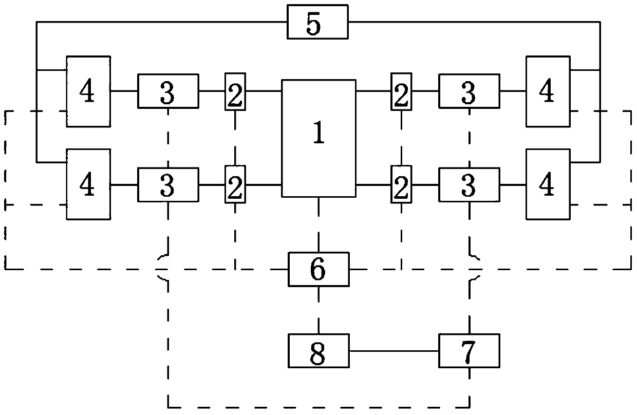
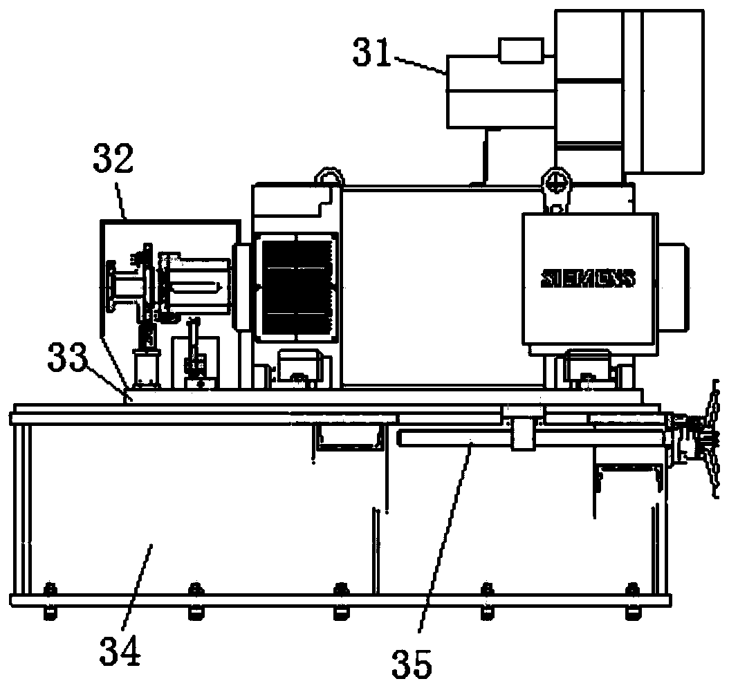
[0017] Such as Figure 1-2 As shown, a four-wheel drive bridge assembly test bench system of the present invention, the four-wheel drive bridge assembly test bench system tests the electric new energy vehicle 1, and the electric new energy vehicle 1 is controlled and operated by the central control system. It is composed of an electrical system and a control system, the electrical system is composed of a dynamometer 3, a drive system 4, and a power supply system 5, the drive system 4 is connected to the dynamometer 3, and the power supply system 5 is connected to the drive system 4 Connect; the control system is made up of a torque sensor 2, a real-time system 6, a data acquisition device 7, and a host computer 8, and the torque sensor 2 is arranged between the dynamometer 3 and the automobile 1, and the real-time system 6 is connected with the vehicle 1 respectively. The drive system 4 and the torque sensor 2 communicate. The data acquisition device 7 is provided with a varie...


PUM


Abstract

The invention discloses a test rack system for a four-wheel-drive bridge assembly. The test rack system for the four-wheel-drive bridge assembly is used for testing an electric new energy automobile, the electric new energy automobile is controlled by a central control system to operate and consists of an electric system and a control system, the electric system consists of a power measuring device, a driving system and a power supply system, the driving system is connected with the power measuring device, and the power supply system is connected with the driving system; and the control system consists of a torque sensor, a real-time system, a data collection device and an upper computer. The structure can complete test items which are completed by a traditional two-wheel-drive rack and also has the functions such as free distribution of power between shafts and free distribution and simulation of power between wheels, the system is directly connected with the central control system of the automobile through a computer, data collection and control can be carried out by using functions of the automobile, the production cost of enterprises is saved, and simultaneously, the purchase cost of users is reduced.

Description

technical field [0001] The invention belongs to an automobile drive test device, in particular to a four-wheel drive bridge assembly test bench system. Background technique [0002] New energy vehicles refer to the use of unconventional vehicle fuels as power sources (or the use of conventional vehicle fuels and new vehicle power devices), and the comprehensive vehicle power control and advanced technology in driving, the formation of advanced technical principles, with Automobiles with new technology and new structure. Electric VehiclesBlade Electric Vehicles (BEV) is a vehicle that uses a single battery as the energy storage power source. It uses the battery as the energy storage power source, and supplies electric energy to the motor through the battery to drive the motor to run, thereby driving the car. . The central control system of the new energy vehicle can control the work of the car and implement various information during the monitoring work; for the existing fo...

Claims


Application Information

Patent Timeline
IPC IPC(8): G01M17/007G01L3/24
CPCG01L3/242G01M17/007
Inventor 李锋俞梦婷毛柯柯范旭
Owner 南通常测机电设备有限公司
Learn More