Method for detecting far-field laser spot image

A technology of laser spot and detection method, which is applied in the field of far-field laser spot image detection, can solve the problems of beam deviation from the field of view of a receiving antenna, interruption of communication links, etc., to ensure real-time smoothness, improve detection accuracy, and improve detection efficiency Effect

Inactive Publication Date: 2019-09-17
XIAN UNIV OF TECH
View PDF1 Cites 25 Cited by
  • Summary
  • Abstract
  • Description
  • Claims
  • Application Information

AI Technical Summary

Problems solved by technology

[0004] The purpose of the present invention is to provide a detection method for far-field laser spot images, which solves the problem that the laser beam is affected by atmospheric turbulence after long-distance transmission in the current wireless laser communication, which makes the beam deviate from the field of view of the receiving antenna, resulting in communication problems. link down problem

Method used


Image

  • Method for detecting far-field laser spot image
  • Method for detecting far-field laser spot image
  • Method for detecting far-field laser spot image

Examples


Embodiment 1

[0081] A detection method of a far-field laser spot image, characterized in that it is specifically implemented according to the following steps:

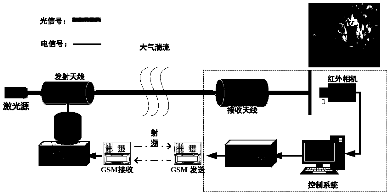
[0082] Step 1: Build the far-field laser spot detection and control system on the wireless laser communication APT system experiment. The transmitting end of the far-field laser spot detection and control system is composed of a 1550nm laser, a two-dimensional composite axis aiming platform and a transmission antenna. The transmitting antenna is fixed on the two-dimensional compound-axis pan-tilt, and the two-dimensional compound-axis pan-tilt is controlled by the PC control system combined with the GSM radio frequency module, so that the transmitting antenna moves in the horizontal and pitch directions to keep the link unblocked; the receiving end has an aperture of 30cm Cassegrain antenna, GSM radio frequency module, Xenics infrared camera and spot detection control system,

[0083] The Xenics infrared camera with the exposure ti...

Embodiment 2

[0110] A detection method of a far-field laser spot image, characterized in that it is specifically implemented according to the following steps:

[0111] Step 1: Build the far-field laser spot detection and control system on the wireless laser communication APT system experiment. The transmitting end of the far-field laser spot detection and control system is composed of a 1550nm laser, a two-dimensional composite axis aiming platform and a transmission antenna. The antenna is fixed on the two-dimensional composite axis gimbal, and the two-dimensional composite axis gimbal is controlled by the PC control system combined with the GSM radio frequency module, so that the transmitting antenna moves in the horizontal and pitch directions to keep the link open; the receiving end has an aperture of 30cm Cassegrain antenna, GSM radio frequency module, Xenics infrared camera and spot detection control system,

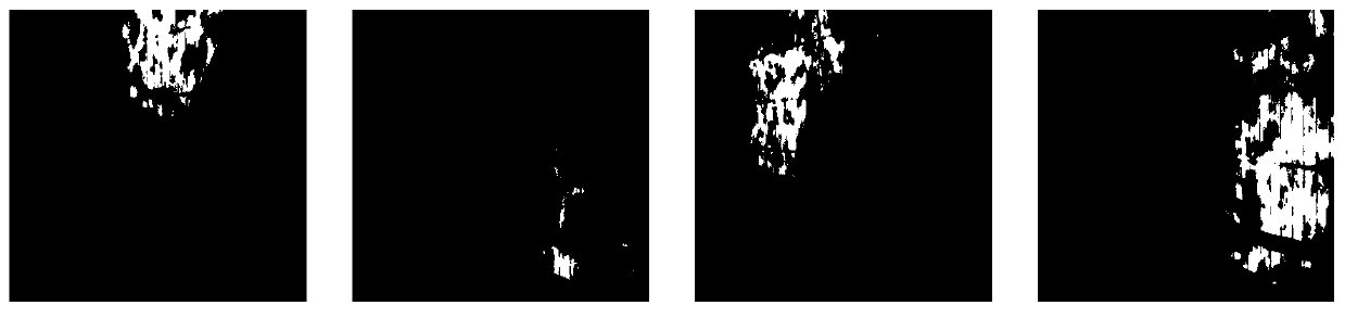
[0112] The exposure time is 11800Xenics infrared camera for interval sampl...


PUM


Abstract

The invention discloses a method for detecting a far-field laser spot image, which is specifically implemented according to the following steps: 1, performing interval sampling by using a Xenics infrared camera, and outputting a standard video signal by using a CCD (Charge Coupled Device) detector; 2, comparing the light spots under different transmitting powers and distances; 3, preprocessing the irregular far-field laser spot image; 4, extracting a target light spot; and 5, calculating a gradient through a Laplace operator to extract a light spot target, carrying out simulation analysis on a far-field laser light spot, designing and applying an algorithm, finally detecting a position coordinate center of the light spot, detecting a difference value of the coordinate center of the light spot, and realizing re-alignment and tracking of the light beam. The invention discloses a method for detecting a far-field laser spot image, which effectively improves the detection precision, improves the detection efficiency of a far-field laser spot, and ensures that a communication link is smooth in real time.

Description

technical field [0001] The invention belongs to the technical field of wireless laser communication, and in particular relates to a detection method of a far-field laser spot image. Background technique [0002] Wireless laser communication has many advantages, such as huge communication capacity, fast transmission rate, strong anti-interference ability, good concealment, no need for spectrum license, etc. As one of the communication solutions, it has also been widely used in various fields, especially in the military field. Traditional radio communications are vulnerable to eavesdropping and jamming, which has a huge impact on military operations. Wireless laser communication technology combined with other communication methods can effectively solve the above problems, so all countries are scrambling to study the application of wireless laser communication in military affairs. [0003] While having the above advantages, there are also unavoidable shortcomings. The current...

Claims


Application Information

Patent Timeline
Patent Type & Authority Applications(China)
IPC IPC(8): G06T7/00G06T7/11G06T7/136G06T7/62G06T5/00G06T5/20G06T5/30
CPCG06T5/002G06T5/20G06T5/30G06T7/0002G06T2207/10048G06T2207/20024G06T7/11G06T7/136G06T7/62
Inventor 柯熙政景永康
Owner XIAN UNIV OF TECH
Why Eureka
Try Eureka