
Modular multilevel topology and its control method based on coupled inductor dual-buck sub-module

A modular multi-level, coupled inductor technology, applied in electrical components, output power conversion devices, AC power input conversion to DC power output, etc., can solve the short circuit of DC side capacitors, output AC voltage distortion, and reduce power quality etc. to achieve the effects of reducing voltage distortion rate, improving effectiveness and reliability, and improving dynamic performance

Active Publication Date: 2020-07-31
扬州永茂电力建设有限公司 +1
View PDF2 Cites 0 Cited by
  • Summary
  • Abstract
  • Description
  • Claims
  • Application Information

AI Technical Summary

Problems solved by technology

[0003] However, the traditional modular multilevel converter uses a half-bridge structure as a sub-module, which has the disadvantage of bridge arm direct connection, that is, when the upper and lower switch tubes of the bridge arm are turned on at the same time, the DC side capacitor is short-circuited, causing system failure
In order to overcome the above shortcomings, it is necessary to introduce a dead zone to ensure that the previous switch is completely turned off and then turn on its complementary switch. However, the dead zone also brings narrow pulses, resulting in distortion of the output AC voltage and reducing the power quality. It is especially serious at high switching frequency, so further improvement of modular multilevel topology is needed to suppress the distortion problem caused by dead zone

Method used


Image

  • Modular multilevel topology and its control method based on coupled inductor dual-buck sub-module
  • Modular multilevel topology and its control method based on coupled inductor dual-buck sub-module
  • Modular multilevel topology and its control method based on coupled inductor dual-buck sub-module

Examples


Embodiment Construction

[0024] The present invention is described in detail below in conjunction with the accompanying drawings.

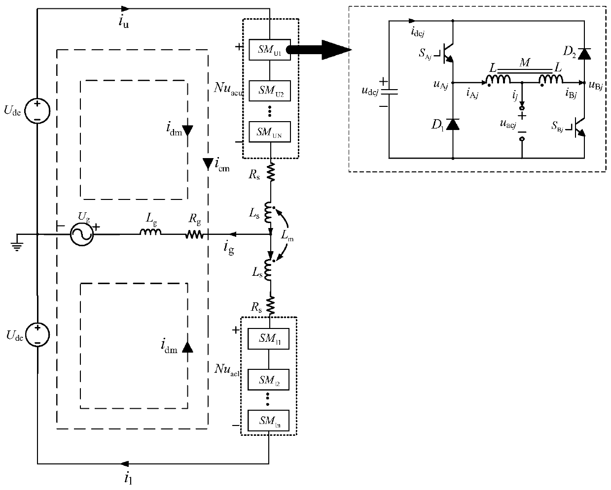
[0025] Such as figure 1 As shown on the left side of , the topology of the modular multilevel converter based on the coupled inductor double-step-down sub-module of the present invention includes: two groups of identical coupled-inductor double-step-down sub-modules and coupled inductor L m . Each group of sub-modules includes N end-to-end sub-modules. The first group of submodules SM u1 to SM uN Located in the upper bridge arm, and the first submodule SM U1 The first end of the terminal is connected to the positive pole of the external DC system, and the second group of sub-modules SM l1 to SM lN Located in the lower bridge arm, and the Nth sub-module SM lN The tail end is connected to the negative pole of the external DC system. Wherein, the external direct current system includes a direct current voltage source. The Nth submodule SM in the first group of submo...


PUM


Abstract

The invention discloses a modular multi-level topological structure and a control method based on coupled inductance double step-down sub-modules. The upper and lower bridge arms of this topology structure each include N coupled inductor double-step-down sub-modules capable of outputting three levels, which avoids the output voltage distortion caused by the direct connection of the bridge arm and the dead zone of the traditional half-bridge sub-module, and effectively improves the conversion efficiency. output power quality and power density of the device. In the single-phase topology, the remote ends of the upper and lower bridge arms are used as the common DC terminal of the converter; the respective sub-modules of the upper and lower bridge arms are connected in series and coupled inductors, and the middle point is connected to the external AC system. In addition, in the control method of the above topological structure, the voltage loop is used to adjust the common-mode voltage, the current loop is used to adjust the common-mode and differential-mode current, and an additional current loop is used to control the common-mode current of the sub-modules to obtain a certain DC bias enables the sub-module to maintain a continuous current condition, which improves the dynamic performance of the topology and ensures its safe and reliable operation.

Description

technical field [0001] The invention belongs to the technical field of high-voltage and high-power power electronics, and mainly relates to a modular multi-level topology structure and a control method based on coupled inductor double-buck sub-modules. Background technique [0002] Modular multilevel converter has a series of advantages such as common DC interface, strong fault tolerance, output voltage close to sine wave, bidirectional flow of energy and four-quadrant operation, etc., so it is widely used in high voltage direct current transmission system, static var compensation Devices, unified power flow controllers, medium and high voltage motor drives and active filters and a series of high voltage and high power applications. [0003] However, the traditional modular multilevel converter uses a half-bridge structure as a sub-module, which has the disadvantage of bridge arm through-circuit, that is, when the upper and lower switch tubes of the bridge arm are turned on ...

Claims


Application Information

Patent Timeline
Patent Type & Authority Patents(China)
IPC IPC(8): H02M7/5387H02M7/483H02M1/38
CPCH02M1/38H02M7/483H02M7/53871H02M1/0025H02M7/4835
Inventor 孙毅超吕丹丁楠木王琦
Owner 扬州永茂电力建设有限公司
Learn More