
Roof type air conditioning system based on solar energy and waste heat recovery

A waste heat recovery and air-conditioning system technology, which is applied in heat recovery systems, air-conditioning systems, ventilation and heating energy recovery systems, etc., can solve the problems of exhaust energy waste, high energy consumption of fresh air, and inability to use fresh air for cooling, etc., to achieve reduction The effect of opening time, convenient management and compact structure

Inactive Publication Date: 2019-09-20
ANHUI UNIV OF SCI & TECH
View PDF6 Cites 3 Cited by
  • Summary
  • Abstract
  • Description
  • Claims
  • Application Information

AI Technical Summary

Problems solved by technology

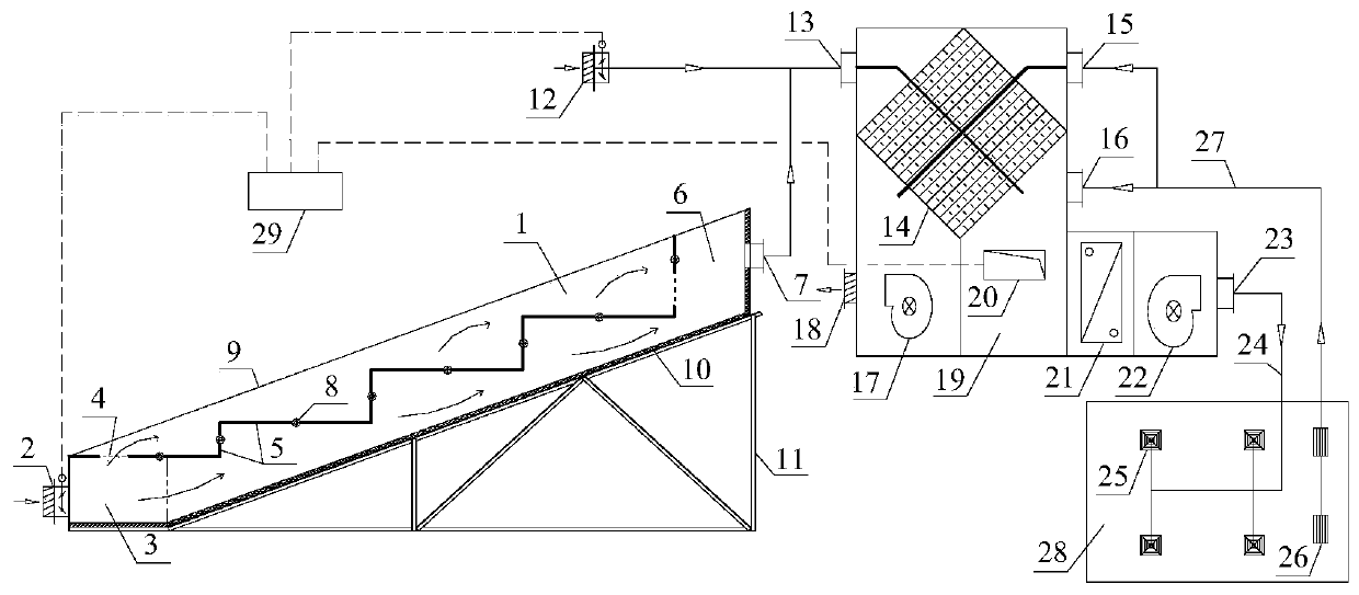
[0003] The present invention aims at the problems of high energy consumption of fresh air, waste of exhaust air energy and inability to use fresh air for cooling in the prior art, and provides a roof-type air conditioning system based on solar energy and waste heat recovery, that is, solar heaters, waste heat recovery of exhaust air and a new A new system integrating air cooling

Method used


Image

  • Roof type air conditioning system based on solar energy and waste heat recovery
  • Roof type air conditioning system based on solar energy and waste heat recovery
  • Roof type air conditioning system based on solar energy and waste heat recovery

Examples


Embodiment Construction

[0019] In order to better understand the present invention, the present invention will be described more fully below in conjunction with the accompanying drawings. The following examples are only used to more clearly illustrate the technical solutions of the present invention, and are not intended to limit the protection scope of the present invention. All equivalent structural transformations made using the description of the present invention and the contents of the accompanying drawings are directly or indirectly used in other related technologies. fields, are included in the patent protection scope of the present invention.

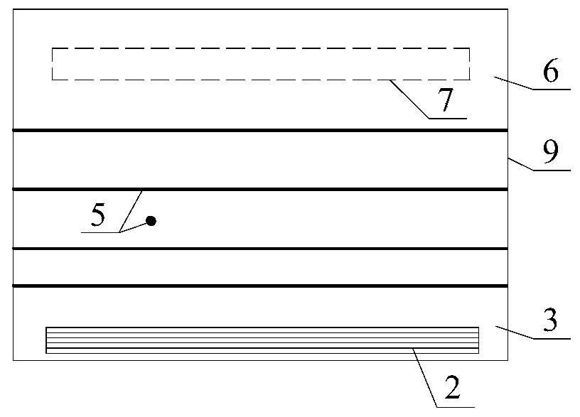
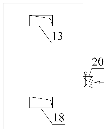
[0020] The present invention provides a roof-mounted air-conditioning system based on solar energy and waste heat recovery. In summer working conditions, the fresh air enters the high-efficiency plate heat exchanger 14, and after obtaining the waste heat of the exhaust air, it is mixed with the indoor return air, and then the surface air is exchanged. ...


PUM


Abstract

The invention discloses a roof type air conditioning system based on solar energy and waste heat recovery. The roof type air conditioning system based on solar energy and waste heat recovery can work under summer working conditions, winter working conditions and transition season working conditions. Under the summer working conditions, fresh air enters an efficient plate type heat exchanger, waste heat of exhaust air is obtained and is then mixed with indoor return air, and then cooling treatment is carried out through a surface type air heat exchanger to enter a room through an air supply pipe and an air supply outlet; and the exhaust air enters the efficient plate type heat exchanger through an air conditioner room air return opening and an air return pipeline, and waste heat is transferred to the fresh air and is then discharged to the atmosphere. Under the winter working conditions, fresh air is preheated for one time through an enhanced solar air heater, and then the fresh air is subjected to secondary preheating by waste heat of exhaust air through the efficient plate type heat exchanger and is then mixed with indoor return air, and finally, heating treatment is carried out through the surface type air heat exchanger and then enters the room through an air supply pipe and an air supply opening. Under the transition season working conditions, the system operates with totally fresh air. Under the summer working conditions, the winter working conditions and the transition season working conditions, the opening and closing of a fresh air opening are converted by an intelligent controller. The roof type air conditioning system based on solar energy and waste heat recovery has the advantages of being energy-saving, environment-friendly, compact in structure, low in noise, high in automation degree and the like.

Description

technical field [0001] The invention relates to the technical field of waste heat recovery air conditioning equipment and the application of clean solar energy resources, in particular to a rooftop air conditioning system based on solar energy and waste heat recovery. Background technique [0002] As people's requirements for indoor environment comfort gradually increase, air-conditioning systems have been widely used. For the air-conditioning systems in multi-storey or single-storey buildings such as lecture halls, multi-functional halls, shopping malls, exhibition halls, theaters, factories, stadiums, etc., due to the high density of people, the fresh air volume of the air-conditioning system is required to be large, so the air-conditioning system can higher consumption. In order to maintain the balance of indoor air volume, the air conditioning system in these places also has a large exhaust air volume. If it is directly exhausted, a lot of cold and heat will be wasted. ...

Claims


Application Information

Patent Timeline
IPC IPC(8): F24F5/00F24F12/00F24F11/89
CPCF24F5/0046F24F12/006F24F2005/0064F24F11/89Y02B10/20Y02B30/56Y02A30/272
Inventor 许登科范铭静韦志文
Owner ANHUI UNIV OF SCI & TECH
Learn More