Logic device, logic assembly and manufacturing method of logic device

A technology of a logic device and a manufacturing method, applied in the field of microelectronics, can solve the problems of insufficient flexibility and high energy consumption of logic devices, and achieve the effects of strong practicability and broad application prospects.

Pending Publication Date: 2019-09-20
叶建国
View PDF0 Cites 2 Cited by
  • Summary
  • Abstract
  • Description
  • Claims
  • Application Information

AI Technical Summary

Problems solved by technology

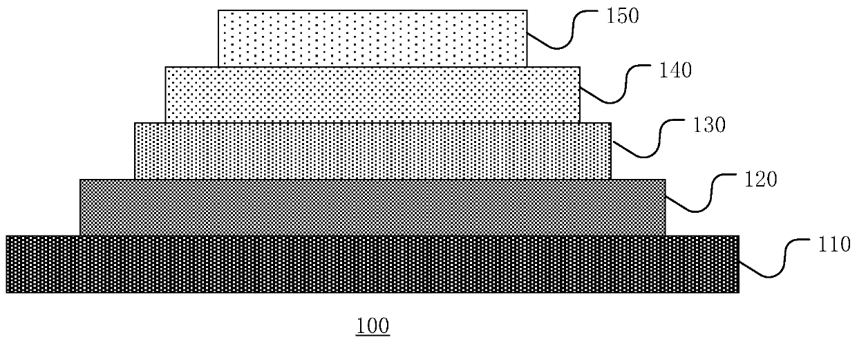
[0005] In view of this, the present invention provides a logic device based on multiferroic magnetoelectric coupling and spin-orbit coupling effects to solve the problems of insufficient flexibility and high energy consumption of logic devices in the prior art

Method used


Image

  • Logic device, logic assembly and manufacturing method of logic device
  • Logic device, logic assembly and manufacturing method of logic device
  • Logic device, logic assembly and manufacturing method of logic device

Examples


Embodiment Construction

[0050] The following disclosure provides many different implementations, or examples, for implementing different features of the application. Specific examples of components or arrangements are described below to simplify the present disclosure. Of course, these are merely examples and are not intended to limit the invention.

[0051] Furthermore, in the description and claims, the terms "first", "second", etc. are used to distinguish between similar elements, and do not necessarily describe a temporal order, spatial order, hierarchical order, or any other order, should It is to be understood that the terms so used are interchangeable under appropriate circumstances and that the embodiments of the invention described herein are capable of operation in other sequences than described or illustrated herein.

[0052] It should be noted that the term "comprising" used in the claims should not be interpreted as limited to the means listed below, it does not exclude other elements o...


PUM


Abstract

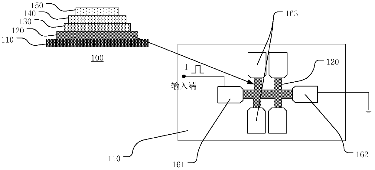
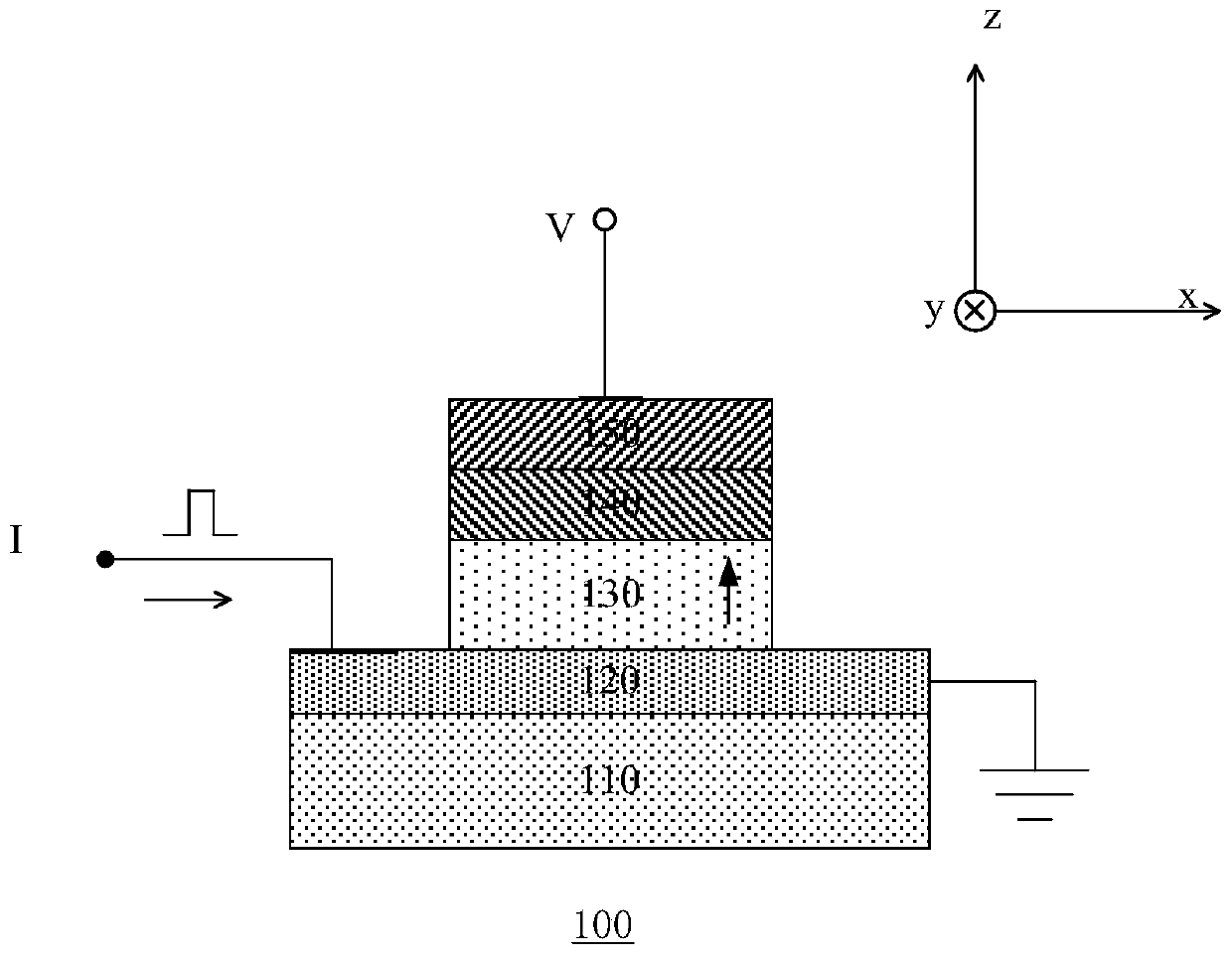
The invention provides a logic device and a manufacturing method thereof. The logic device comprises a substrate, a heavy metal layer, a ferromagnetic layer, a multiferroic layer and an oxide layer, wherein the heavy metal layer comprises a cross structure of which the outer side is provided with a corresponding electrode; and the resistance of the heavy metal layer is changed by changing the direction of an electric field applied between the oxide layer and the heavy metal layer. Specifically, the substrate is a flexible substrate, and has the advantages of being resistant to extrusion, bendable and the like; and the control of the electric field on a critical current of spin-orbit coupling is realized at the room temperature through a multiferroic material, so that a spin-orbit coupling signal is effectively controlled. The effect of the logic device is changed by using different oxidation state interfaces (oxide layers), and the control of an input voltage on the critical current of the spin-orbit coupling makes a difference, so that an N-type or P-type logic operation function can be achieved; the light, portable and low-power logic device can be obtained; and logic devices can also be combined to obtain a logic assembly integrating N-type and P-type logic functions.

Description

technical field [0001] The invention relates to the technical field of microelectronics, in particular to a logic device based on multiferroic magnetoelectric coupling and spin-orbit coupling effects and a manufacturing method thereof. Background technique [0002] Traditional electronics is based on the charge properties of electrons, and people realize information storage and logic processing through the control of electronic charges. However, with the gradual miniaturization of electronic devices, the influence of quantum effects and energy loss is becoming more and more obvious, and traditional electronic devices can no longer meet the needs of development. [0003] The advantages of spintronic devices such as non-volatility, low energy consumption and high integration make them develop rapidly. The high computing power and low energy consumption of spintronic devices in information processing are incomparable to traditional semiconductor electronic devices. Spin-orbit ...

Claims


Application Information

Patent Timeline
Patent Type & Authority Applications(China)
IPC IPC(8): H01L29/66H01L21/34H01L43/02H01L43/12
CPCH01L29/66984H01L29/66969H10N50/80H10N50/01
Inventor 叶建国
Owner 叶建国
Why Eureka
Try Eureka